Shutter driving device for camera module

A driving device and camera module technology, applied in shutter, camera, optics and other directions, can solve the problems of increasing the driving force of the solenoid valve, increasing the power, limiting the camera module, etc., to achieve the effect of shortening the stroke, reducing power consumption, and reducing the size

Active Publication Date: 2015-05-20
YANTAI RAYTRON TECH
View PDF7 Cites 0 Cited by
  • Summary
  • Abstract
  • Description
  • Claims
  • Application Information

AI Technical Summary

Problems solved by technology

[0005] There are some disadvantages in the above-mentioned traditional shutter driving devices, figure 1 The disadvantage of the rotary shutter driving device shown is that the shutter blades must be driven by the motor to rotate to realize the opening and closing of the aperture light path. The volume of the motor and the space occupied by the shutter blades after they are rotated out limit the miniaturization of the camera module; figure 2 The disadvantage of the sliding shutter drive device is that the rocker must be long enough to meet the travel requirements of the shutter blades. After the rocker is lengthened, the arm of force increases, resulting in an increase in the driving force of the solenoid valve. Only a larger solenoid valve can be used, which eventually leads to a loss of power. increase, the volume will also increase rapidly, which is not conducive to the development of low power consumption and miniaturization of camera modules

Method used


Image

  • Shutter driving device for camera module
  • Shutter driving device for camera module
  • Shutter driving device for camera module

Examples


Embodiment 1

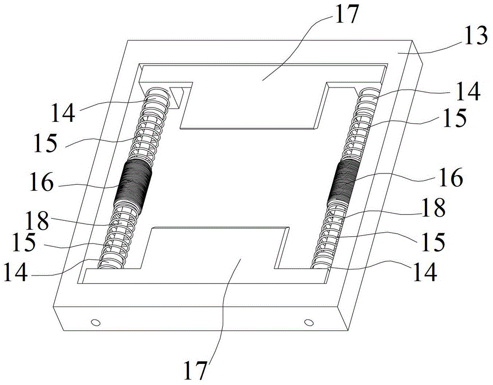
[0029] Such as image 3 , Figure 4 As shown, a shutter driving device for a camera module according to the present invention includes a frame 13, two "T" shutter blades 17, four permanent magnets 14, four springs 15, two guide rods 18, two An electromagnet 16, a light-passing area 19, the frame 13 is a rectangular frame structure, and two fixing holes are respectively arranged on its two opposite faces, and the "T" type shutter blade 17 is composed of a transverse "T" cap And the "T" structure of the longitudinal "T" body, the two "T" shutter blades 17 are symmetrically distributed in the frame 13, and the horizontal "T" cap of each "T" shutter blade 17 There is a through hole at each of the two ends, the through hole is aligned with the fixing hole on the frame 13, and a hollow cylindrical permanent magnet 14 is respectively fixed along the longitudinal "T" body direction at each through hole. A spring 15 is fixed on each permanent magnet, and a hollow cylindrical electrom...

Embodiment 2

[0034] Figure 7As shown, the shutter driving device for the camera module described in the second embodiment includes a frame 13, two horizontal "middle" shutter blades 17, two permanent magnets 14, two springs 15, two guide rods 18, An electromagnet 16, a light-passing area 19, the frame 13 is a rectangular frame-like structure, and two fixing holes are respectively arranged on its two opposite faces, and the described horizontal "middle" word shutter blade 17 includes the blade body and its two The two cantilevers at the end, the two horizontal "middle" shutter blades 17 are symmetrically distributed in the frame 13, and there is a through hole on the cantilever of each horizontal "middle" shutter blade 17, the through hole The hole is aligned with the fixing hole on the frame 13, and one guide rod is fixed in the fixing hole of the frame 13 after directly passing through the through hole of the horizontal "middle" shutter blade, and a hollow cylindrical shape is fixed in t...


PUM


Abstract

The invention relates to a shutter driving device for a camera module, which comprises a framework, shutter blades, permanent magnets, springs, two straight line sidling type guide structures, an electromagnet and a light through region, wherein the shutter blades are positioned on the straight line sliding type guide structures and can slide on the straight line sliding type guide structures, the electromagnet is fixed at the middle of the straight line sliding type guide structures, the permanent magnets are fixed on the shutter blades, opposite attract or repellent action force between the permanent magnets and the electromagnet is generated by applying different directions of current on the electromagnet to drive the sliding of the shutter blades and realize the opening and the closing of the shutter blades, and a light path is opened or closed. The electromagnet is adopted to drive, the shutter blades slide in a straight line manner by the guide structures, so that the size of the shutter driving device is reduced, the shutter stability is improved, and the miniaturization of electronic imaging equipment is finally guaranteed.

Description

technical field [0001] The invention relates to a shutter driving device, in particular to a shutter driving device for a camera module. Background technique [0002] In recent years, the size of the camera module has shrunk with the development of technology, but the size of the shutter driver still restricts the size of the camera module, especially in the infrared industry. The traditional shutter driving device uses a motor to drive the blades to rotate or a solenoid valve to drive the blades to move to realize the opening and closing of the shutter. [0003] figure 1 It is a perspective view of the structure of a conventional rotary shutter drive device for a camera module. As shown in the figure, the device includes a motor 1 , a single-handle shutter blade 2 , an image plane unit 3 and a bracket 4 . The motor 1 is fixed on the bracket 4, and the single-handle shutter blade 2 is fixed on the shaft of the motor 1. The single-handle shutter blade 2 rotates under the dr...

Claims


Application Information

Patent Timeline
Patent Type & Authority Patents(China)
IPC IPC(8): G03B9/14
Inventor 孙同波杨秀武熊笔锋王宏臣
Owner YANTAI RAYTRON TECH
Why Eureka
Try Eureka