MEMS linear electrostatic driving technology

An electrostatically driven, linear technology, used in optical components, optics, instruments, etc., to solve problems such as non-linear electrostatic forces/torques

Active Publication Date: 2020-04-10
NORTHWESTERN POLYTECHNICAL UNIV
View PDF8 Cites 0 Cited by
  • Summary
  • Abstract
  • Description
  • Claims
  • Application Information

AI Technical Summary

Problems solved by technology

The nonlinear electrostatic force / moment is not realized in this method, but the approximate linearization of the driving displacement is achieved by means of a complex nonlinear stiffness support structure

Method used


Image

  • MEMS linear electrostatic driving technology
  • MEMS linear electrostatic driving technology
  • MEMS linear electrostatic driving technology

Examples


Embodiment 1

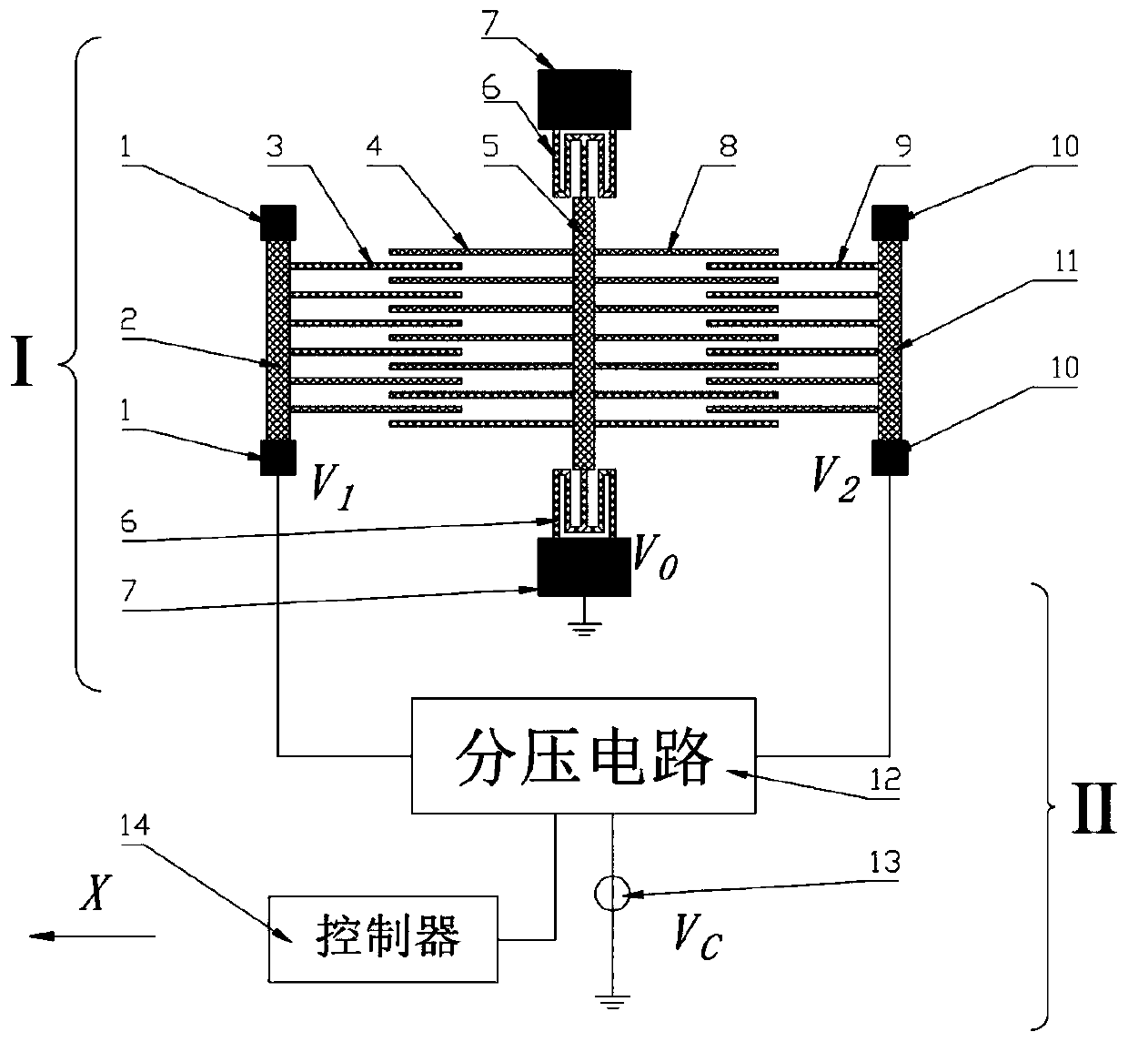
[0027] Embodiment 1: see figure 1 , the comb-tooth structure of the MEMS linear electrostatic drive technology in this embodiment is a straight comb-tooth structure.

[0028] The electrostatic driving system in this embodiment mainly includes: a comb structure part I and a driving circuit part II; the comb structure part I is composed of a movable comb part in the center and fixed comb groups on both sides; The movable comb part in the center mainly includes a middle support body 5, a left movable comb tooth 4, a right movable comb tooth 8, an elastic beam 6 and a middle anchor point 7, and the left movable combs are symmetrically distributed on both sides of the middle support body 5. Teeth 4 and right movable comb teeth 8, the middle support body 5 is fixed on the middle anchor point 7 through the elastic beam 6; the left fixed comb teeth group mainly includes the left fixed comb teeth 3, the left support body 2 and the left Anchor point 1, the left fixed comb teeth 3 are f...

Embodiment 2

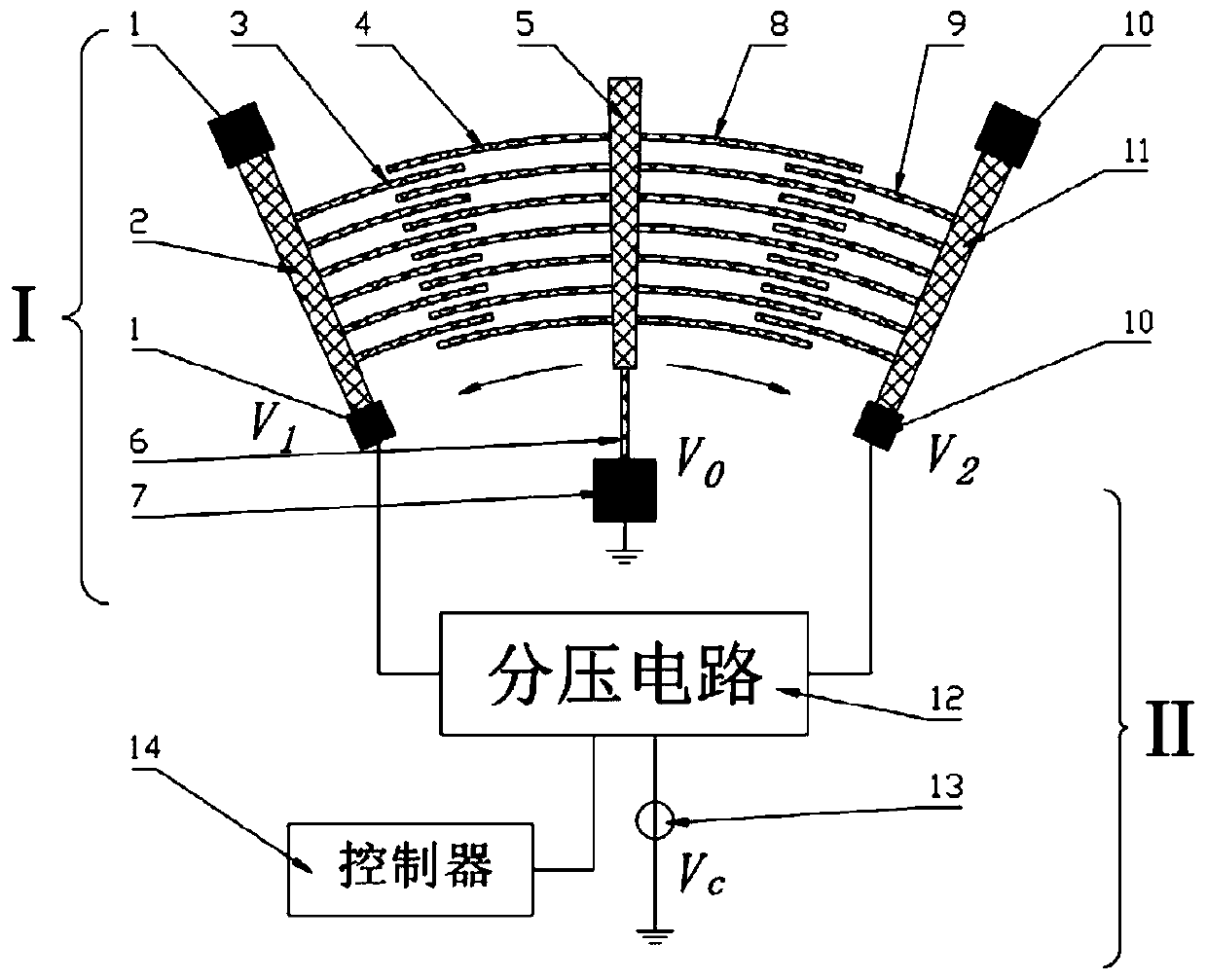
[0042] Embodiment 2: see figure 2 , the comb structure of the MEMS linear electrostatic drive system in this embodiment is an arc-shaped comb structure.

[0043] The electrostatic driving system in this embodiment mainly includes: a comb structure part I and a driving circuit part II; the comb structure part I is composed of a movable comb part in the center and fixed comb groups on both sides; The movable comb part in the center mainly includes a middle support body 5, a left movable comb tooth 4, a right movable comb tooth 8, an elastic beam 6 and a middle anchor point 7, and the left movable combs are symmetrically distributed on both sides of the middle support body 5. Teeth 4 and right movable comb teeth 8, the middle support body 5 is fixed on the middle anchor point 7 through the elastic beam 6; the left fixed comb teeth group mainly includes the left fixed comb teeth 3, the left support body 2 and the left Anchor point 1, the left fixed comb teeth 3 are fixed on the ...


PUM


Abstract

The invention discloses an MEMS linear electrostatic driving technology, and belongs to the field of micro electro mechanical systems. The technology is realized based on an MEMS linear electrostaticdriving system. The system mainly comprises a comb tooth structure part I and a driving circuit part II. Different driving voltages are connected to the symmetrical fixed comb tooth parts, so that electrostatic force borne by the movable comb tooth part is the sum of lateral electrostatic force generated by the two sets of comb tooth structures connected with the different driving voltages, and the square relation between the electrostatic force and the driving voltages is converted into the sum-difference relation between the electrostatic force and the different driving voltages. The voltagedivision circuit is designed, so that the sum of the two driving voltages is constant. The electrostatic force resultant force borne by the movable comb tooth part and the driving voltage of one pathare in a linear relation, and therefore accurate linear electrostatic driving can be achieved by adjusting the voltage division circuit.

Description

technical field [0001] The invention relates to a MEMS linear electrostatic drive technology based on a comb structure, belonging to the field of micro-electromechanical systems. Background technique [0002] Micro-Electro-Mechanical System (MEMS for short) refers to an independent intelligent system whose internal structure is generally on the order of microns or even nanometers. The structure of MEMS devices is small, and the traditional driving methods are difficult to work in MEMS devices. The commonly used driving methods include electrostatic driving, piezoelectric driving, electromagnetic driving or thermal expansion force driving. Among them, the electrostatic drive has the advantages of low power consumption, simple manufacture, compatibility with integrated circuit (IC) technology, and fast response speed, and is the most common in the MEMS field. [0003] Electrostatic drive uses the electrostatic force / torque between two parallel plates as the driving force, whi...

Claims


Application Information

Patent Timeline
Patent Type & Authority Applications(China)
IPC IPC(8): G02B26/08
CPCG02B26/0858
Inventor 郝永存张钊苑伟政常洪龙
Owner NORTHWESTERN POLYTECHNICAL UNIV
Why Eureka
Try Eureka