Oil discharging device for mining oil storage tank

An oil discharge device and oil storage tank technology, which is applied in the field of mine oil storage tank oil discharge devices, can solve the problems of increasing floor space and increasing costs, and achieves the effect of convenient operation, simple structure, fast, reliable and frequent supply

Inactive Publication Date: 2020-01-31
徐州众信矿业科技有限公司
View PDF7 Cites 0 Cited by
  • Summary
  • Abstract
  • Description
  • Claims
  • Application Information

AI Technical Summary

Problems solved by technology

[0002] In the daily oil distribution process of coal mines, it is necessary to frequently take oil from the oil storage tank. The traditional way of taking oil is to pour it out or use it through an oil pump. The process of pouring out requires a lot of labor for the operator , and the way of using the oil pump requires additional equipment, which increases the cost and increases the floor space

Method used


Image

  • Oil discharging device for mining oil storage tank

Examples


Embodiment Construction

[0014] The present invention will be further described below.

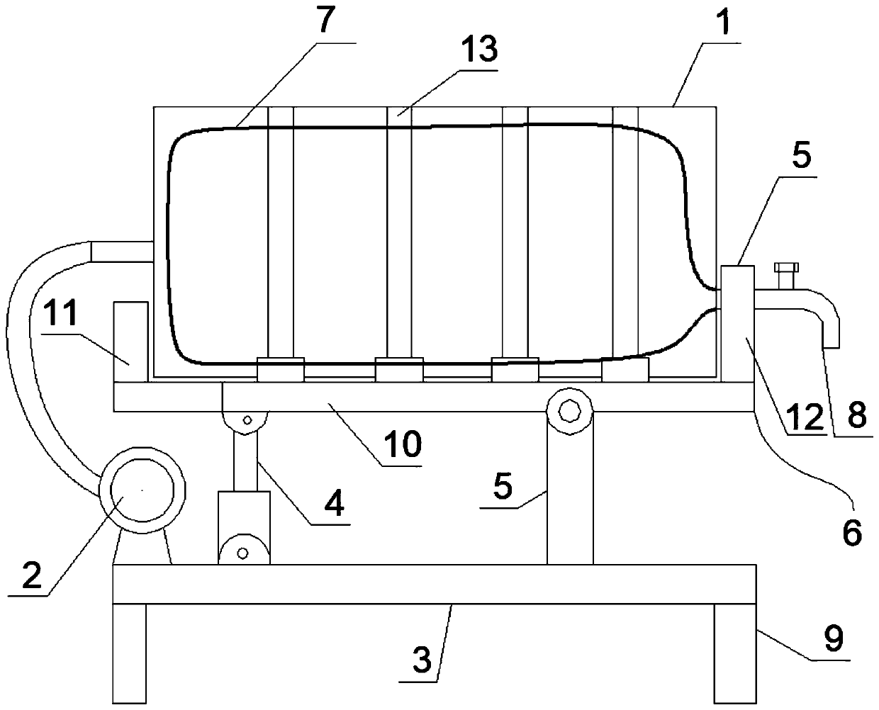
[0015] Such as figure 1 As shown, a mining oil storage tank 1 oil discharge device includes an oil storage tank 1, a support frame and an air compressor. The support frame has a support base plate 3, a pair of left supports fixedly connected to the left part of the support base plate 3 Column 4, a pair of right support columns 5 fixedly connected to the right part of the support base plate 3 and a load-bearing frame 6 arranged above the support base plate 3;

[0016] The left side of the lower part of the bearing frame 6 is hinged to the upper ends of a pair of support columns, and the right side of the lower part is hinged to the upper ends of a pair of right support columns 5;

[0017] The oil storage tank 1 is installed laterally on the bearing frame 6, the inside of the oil storage tank 1 is provided with an elastic rubber bag 7, the elastic rubber bag 7 has an oil port, the oil port is connected with an oil ...


PUM


Abstract

The invention discloses an oil discharging device for a mining oil storage tank. The device comprises an oil storage tank, a supporting frame and an air compressor, wherein the supporting frame is provided with a supporting bottom plate, a pair of left supporting columns fixedly connected to the left part of the supporting bottom plate, a pair of right supporting columns fixedly connected to the right part of the supporting bottom plate, and a bearing frame arranged above the supporting bottom plate; the left side of the lower part of the bearing frame is hinged to the upper ends of one pair of the supporting columns, and the right side of the lower part of the bearing frame is hinged to the upper ends of the pair of right supporting columns; the oil storage tank is transversely installedon the bearing frame, an elastic rubber bag is arranged in the oil storage tank, the elastic rubber bag is provided with an oil port, the oil port is connected with an oil outlet pipeline, and the oiloutlet pipeline is penetrated out from the bottom of the right end of the oil storage tank to the outside of the oil storage tank; the air compressor is installed on the supporting bottom plate, andthe air outlet end of the air compressor communicates with the left part of the inner cavity of the oil storage tank through a hose; and the left supporting columns are lifting hydraulic cylinders. The device is simple in structure and convenient to operate, and frequent feeding of the oil liquid can be quickly and reliably achieved.

Description

technical field [0001] The invention relates to an oil discharge device for a mine oil storage tank. Background technique [0002] In the daily oil distribution process of coal mines, it is necessary to frequently take oil from the oil storage tank. The traditional way of taking oil is to pour it out or use it through an oil pump. The process of pouring out requires a lot of labor for the operator , and the way of using the oil pump requires additional equipment, which increases the cost and increases the floor space. Contents of the invention [0003] Aiming at the above-mentioned problems in the prior art, the present invention provides an oil discharge device for a mine oil storage tank. The device has a simple structure, is easy to operate, and can quickly and reliably realize frequent supply of oil. [0004] In order to achieve the above object, the present invention provides a mining oil storage tank oil discharge device, including an oil storage tank, a support fra...

Claims


Application Information

Patent Timeline
Patent Type & Authority Applications(China)
IPC IPC(8): B65D90/00B65D90/12B65D88/54B65D90/04
CPCB65D88/542B65D88/548B65D90/00B65D90/046B65D90/12
Inventor 张钊郑顺利李春艳孙勇
Owner 徐州众信矿业科技有限公司
Why Eureka
Try Eureka