
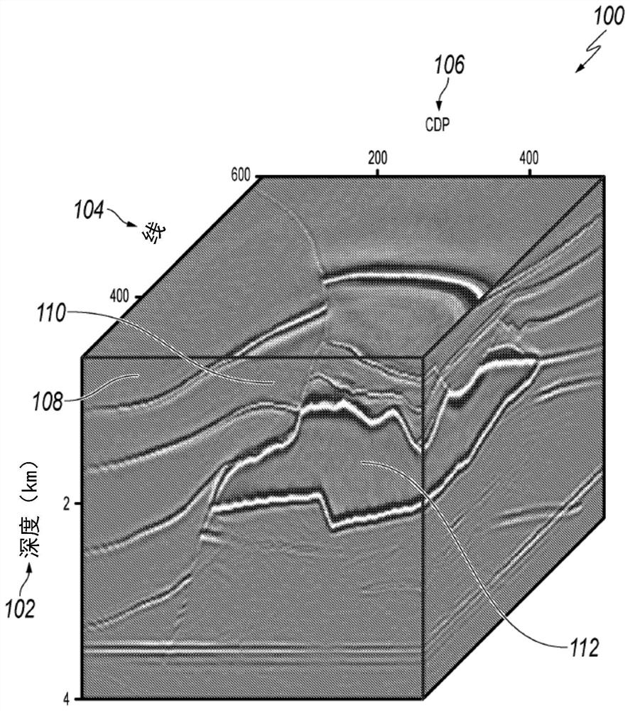
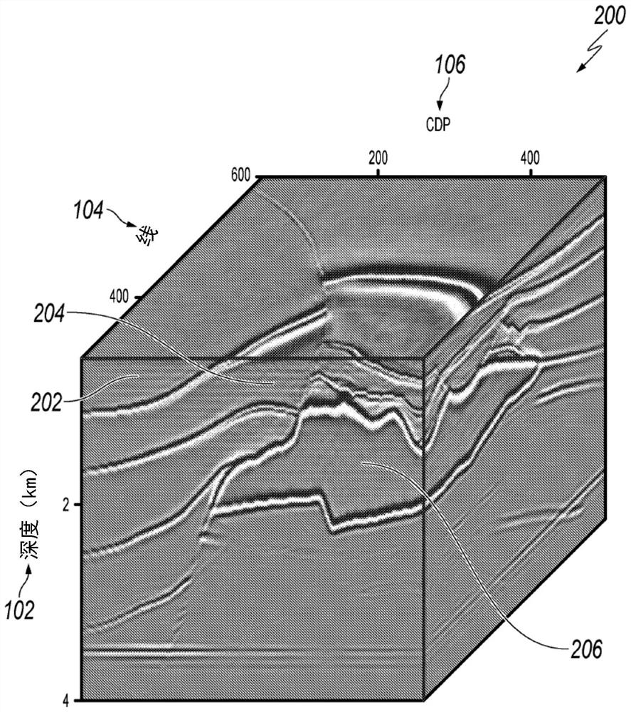
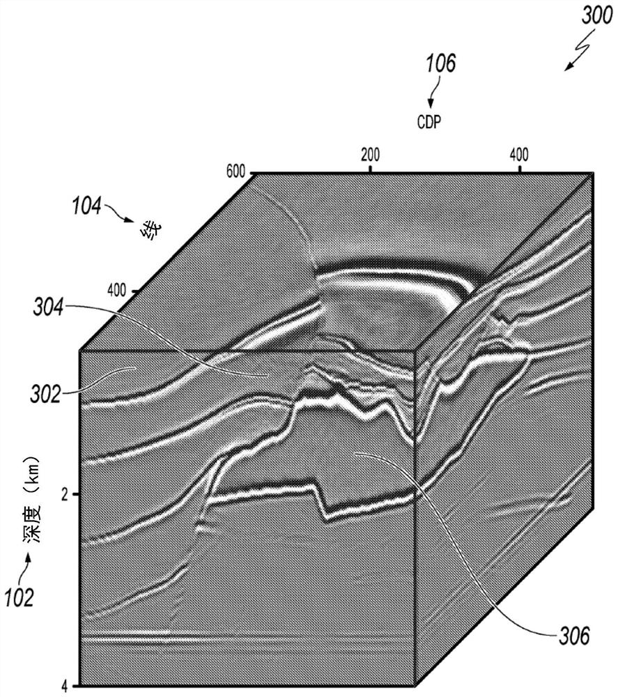
Compressed Seismic Wavefields in 3D Reverse Time Migration

A technology for decompressing and seismic data, used in seismology, seismic signal processing, geophysical measurement, etc., can solve the problem of consuming large computing resources, and achieve the effect of improving imaging results

Active Publication Date: 2022-05-13
SAUDI ARABIAN OIL CO
View PDF4 Cites 0 Cited by
  • Summary
  • Abstract
  • Description
  • Claims
  • Application Information

AI Technical Summary

Problems solved by technology

This approach consumes significant computational resources (e.g., processor cycles, data bus bandwidth, computational memory (e.g., random access memory (RAM)), network bandwidth due to the need to read / write very large data sets to storage locations and data storage space)

Method used


Image

  • Compressed Seismic Wavefields in 3D Reverse Time Migration
  • Compressed Seismic Wavefields in 3D Reverse Time Migration
  • Compressed Seismic Wavefields in 3D Reverse Time Migration

Examples


Embodiment Construction

[0018] The following detailed description describes compressed seismic data and is presented to enable one skilled in the art to make and use the disclosed subject matter in the context of one or more specific implementations. Various modifications, changes, and substitutions may be made to the disclosed implementations and will be apparent to those of ordinary skill in the art, and the general principles defined may be applied to other implementations and applications without departing from the scope of the present disclosure. . In some cases, one or more technical details that are not necessary to gain an understanding of the described subject matter and are within the purview of one of ordinary skill in the art may be omitted so as not to obscure one or more described implementations. The disclosure is not intended to be limited to the implementations described or shown, but is to be accorded the widest scope consistent with the principles and features described.

[0019] ...


PUM


Abstract

A three-dimensional (3D) seismic data set is partitioned into a plurality of 3D source wavefield subsets, each 3D source wavefield subset being stored in an array element of the array. For each array element, decompose the associated 3D source wavefield into smaller data units; randomly shift the data boundaries of the smaller data units; apply folding operations and sample operators to the smaller data units, to prevent smaller data units from overlapping; smooth the folded smaller data units to generate smoothed data; perform a quantization operation on the smoothed data to generate quantized data; and compressively encode the quantized data to generate compressed data. The compressed data associated with each array element is decompressed to generate a 3D seismic output image.

Description

[0001] priority statement [0002] This application claims priority to US Patent Application No. 62 / 484,101, filed April 11, 2017, the entire contents of which are hereby incorporated by reference. Background technique [0003] Seismic imaging is a tool that bounces sound waves off subsurface structures, such as rocks and other sedimentary layers or cavities, to reveal possible oil-bearing formations. Reverse time migration (RTM) is a seismic imaging method that provides accurate imaging in and below regions of complex structures and velocities. In RTM, seismic images are generated by zero-delay cross-correlation of source and receiver wavefields. The source wavefield is computed by forward propagation, while the receiver wavefield is computed by backward propagation. Due to the opposite directions of propagation relative to the source and receiver wavefields, the RTM first computes data for the entire source wavefield and stores this data in a data storage location such as ...

Claims


Application Information

Patent Timeline
Patent Type & Authority Patents(China)
IPC IPC(8): G01V1/28G06T9/00
CPCG01V1/28G06T9/00G01V1/345G06T5/002H04N19/625G01V2210/512H04N19/124H04N19/42G06T5/10H04N19/91G06T9/007
Inventor 孙兵兵刘红伟文森特·艾蒂安嵇绪
Owner SAUDI ARABIAN OIL CO
Learn More