Railway piggyback transportation station foundation structure

A railway and piggyback technology is applied in the field of railway piggyback transport station base structure, which can solve the problems of irregularity and messy loading and unloading sites, and achieve the effects of high loading and unloading operation efficiency and stowage benefits.

Pending Publication Date: 2020-02-04
CHINA RAILWAY SIYUAN SURVEY & DESIGN GRP
View PDF0 Cites 0 Cited by
  • Summary
  • Abstract
  • Description
  • Claims
  • Application Information

AI Technical Summary

Problems solved by technology

[0003] At present, domestic railway piggyback transport vehicles mainly include two types of piggyback transport, QT1 and QT2. Based on the self-loading and self-unloading operation technology of QT1 and QT2 piggyback transport vehicles, the piggyback transport operations at railway stations must meet certain conditions. According to the loading and unloading process of these two types of vehicles, it is necessary to propose a railway piggyback station layout suitable for the loading and unloading process. However, there is currently no specific station base for the piggyback operation of these two types of piggyback vehicles in China. However, in the case of open space, the piggyback transport vehicle is directed to carry out loading and unloading operations based on the operator's judgment on the size of the site, making the loading and unloading site messy and irregular

Method used


Image

  • Railway piggyback transportation station foundation structure
  • Railway piggyback transportation station foundation structure
  • Railway piggyback transportation station foundation structure

Examples


Embodiment Construction

[0034] In order to make the object, technical solution and advantages of the present invention clearer, the present invention will be further described in detail below in conjunction with the accompanying drawings and embodiments. It should be understood that the specific embodiments described here are only used to explain the present invention, not to limit the present invention. In addition, the technical features involved in the various embodiments of the present invention described below can be combined with each other as long as they do not constitute a conflict with each other.

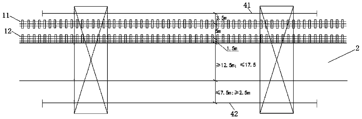
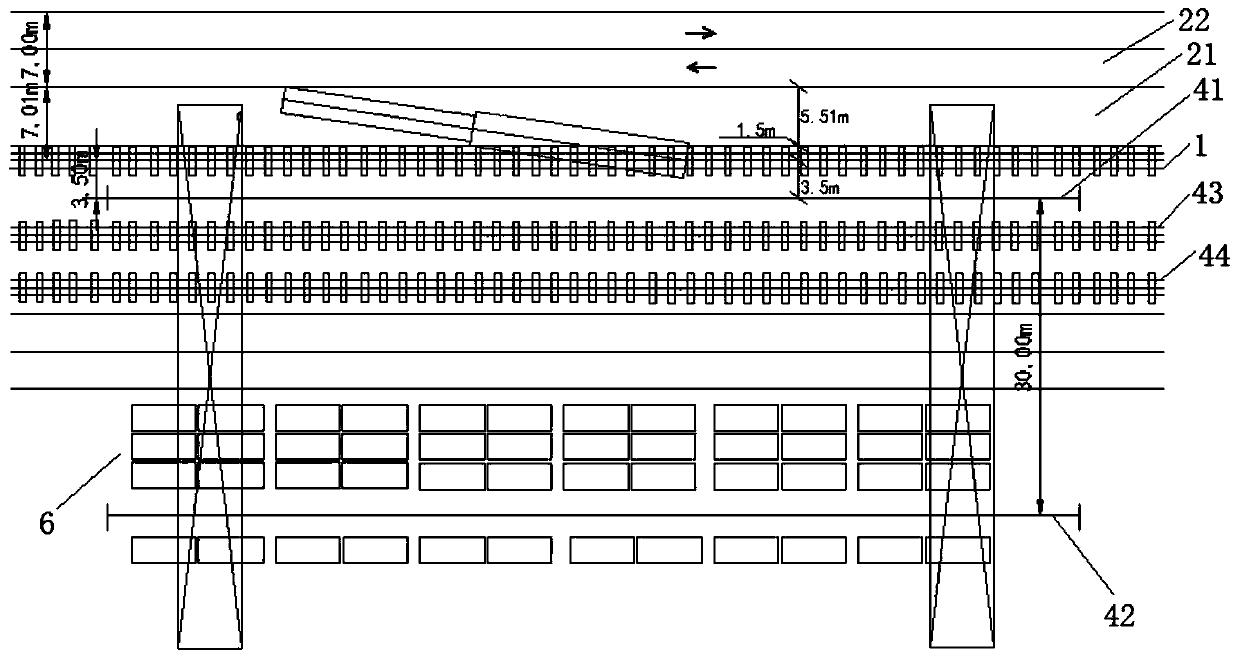
[0035] Such as figure 1 As shown, the base structure of the railway piggyback transportation station includes the railway loading and unloading track 1 and the piggyback operation area 2 arranged side by side, wherein,

[0036] The load-bearing strength of the ground foundation of the piggyback operation area 2 is hardened according to the road truck 7 that can bear a total weight of 60 tons an...


PUM


Abstract

The invention discloses a railway piggyback transportation field station foundation structure. The railway piggyback transportation station foundation structure comprises railway loading and unloadingrails and piggyback working areas which are arranged side by side, wherein the ground foundation of the piggyback working areas is subjected to hardening treatment according to the bearing strength of a highway truck which can bear the total weight of 60 tons and the single axle load of 11.5 tons, the hardened ground is formed, and the height difference between the hardened ground of the piggyback working areas and the upper plane of steel rail bodies of the railway loading and unloading rails is controlled within + / -50 mm; and the distance between the edges, near the railway loading and unloading rails, of the hardened ground of the piggyback working areas and the center line of the railway loading and unloading rails is not less than 1.5 m, and the distance between the edges, far away from the railway loading and unloading rails, of the piggyback working areas and the center line of the railway loading and unloading rails is not less than 7.01 m. By the adoption of the railway piggyback transportation field station foundation structure, the whole column loading and unloading operation efficiency can be improved by about 200%, the operation time can be effectively saved, the siteutilization rate is high, and the transportation efficiency can be improved by more than 30%.

Description

technical field [0001] The invention belongs to the field of railway transportation sites, and more specifically relates to a station base structure for railway piggyback transportation. Background technique [0002] Piggyback transport is a combination of road and railway transportation. Road trucks or containers are directly loaded onto train wagons for transportation, and then unloaded from the wagons after arriving at the destination. This mode of transportation is used in the field of railway transportation and has become very common in Europe and the United States. The development of domestic railway piggyback transportation is still in the initial stage of exploration, and mature piggyback transportation business has not yet been opened, and most of the piggyback transportation vehicles and equipment in Europe and the United States are not suitable for the early development of piggyback transportation in my country, mainly because of the existence of ground station fac...

Claims


Application Information

Patent Timeline
Patent Type & Authority Applications(China)
IPC IPC(8): B65G63/00
CPCB65G63/004
Inventor 孙逊兰建华肖贺荣刘斌叶勇刘文管薇
Owner CHINA RAILWAY SIYUAN SURVEY & DESIGN GRP
Why Eureka
Try Eureka