Floor drain well

A floor drain and well body technology, applied in water/sludge/sewage treatment, drainage structures, buildings, etc., can solve problems such as inconvenience

Inactive Publication Date: 2020-02-04
马鞍山思哲知识产权服务有限公司
View PDF7 Cites 0 Cited by
  • Summary
  • Abstract
  • Description
  • Claims
  • Application Information

AI Technical Summary

Problems solved by technology

[0002] In the traditional floor drain well, the filter plate is directly placed in the well, so that the filter plate is completely immersed in the well body, so that when you want to take out the filter plate, you cannot directly touch the filter plate, and you need to reach into the well to take it out filter plate, very inconvenient

Method used


Image

  • Floor drain well
  • Floor drain well

Examples


Embodiment Construction

[0023] Specific embodiments of the present invention will be described in detail below in conjunction with the accompanying drawings. It should be understood that the specific embodiments described here are only used to illustrate and explain the present invention, and are not intended to limit the present invention.

[0024] In the present invention, unless otherwise specified, the orientation words included in the term such as "up, down, left, right, front, back, inside and outside" only represent the orientation of the term in the normal use state, or the common name understood by those skilled in the art. , and should not be construed as a limitation of this term.

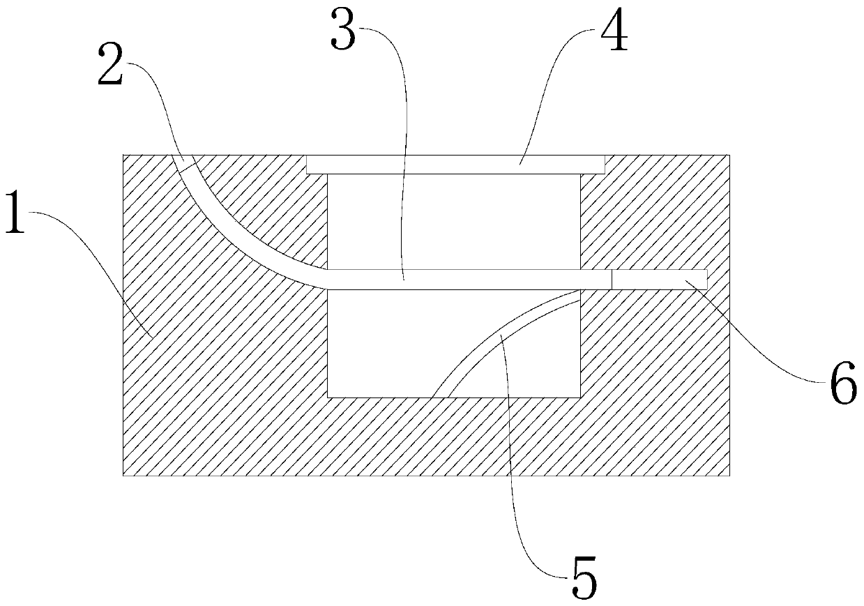
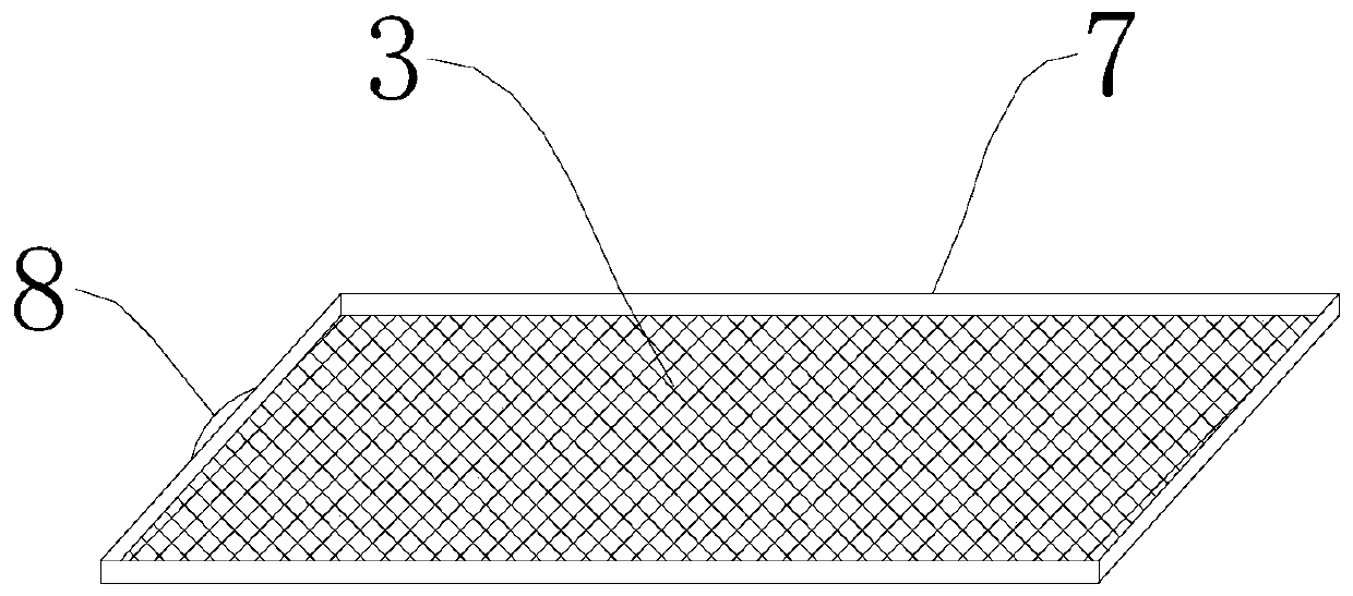
[0025] see Figure 1-2 The floor drain shown in the well includes a well body 1, the front and rear sides of the well body 1 are connected to the sewer, a hollowed-out manhole cover 4 is provided above the well body 1, and a direction is provided on one side of the well body 1. The arc-shaped insertion groove...


PUM


Abstract

The invention discloses a floor drain well, which comprises a well body, the front and rear of the well body are in communication with a sewer, the upper part of the well body is provided with a hollow well cover, one side of the well body is provided with an arc-shaped inserting groove which is bent downwards and communicates with the well body, the well body is arranged on the side face oppositeto the arc-shaped inserting groove to form a clamping groove, and a filter plate with elastic bending performance extends from the arc-shaped inserting groove and inserts into the clamping groove. The floor drain well is not fully submerged in water, and has the advantage of easy removal of a filter plate.

Description

technical field [0001] The invention relates to a water launching device, in particular to a floor drain well. Background technique [0002] In the traditional floor drain well, the filter plate is directly placed in the well, so that the filter plate is completely immersed in the well body, so that when you want to take out the filter plate, you cannot directly touch the filter plate, and you need to reach into the well to take it out Filter plate, very inconvenient. Contents of the invention [0003] The object of the present invention is to provide a floor drain well, which will not be completely submerged in the sewage, and has the advantage of being easy to take out the filter plate. [0004] In order to achieve the above object, the present invention provides a floor drain well, which includes a well body, the front and rear sides of the well body communicate with the sewer, and a hollowed-out well cover is arranged above the well body, which is located on one side ...

Claims


Application Information

Patent Timeline
IPC IPC(8): E03F5/04E03F5/14
CPCE03F5/0404E03F5/0407E03F5/14
Inventor 刘龙云
Owner 马鞍山思哲知识产权服务有限公司
Why Eureka
Try Eureka