Multi-part dovetail repair broach assembly and methods of use

a multi-part, broach technology, applied in the direction of rectilinear broach, broaching machine, manufacturing tools, etc., can solve the problems of inability to repair the slots in assembly using original tools, inability to manufacture tools, and inability to repair the slots in assembly. , to achieve the effect of facilitating lead-in, preventing lateral skewed movement of the broach, and fabricated inexpensively

Inactive Publication Date: 2004-01-13
GENERAL ELECTRIC CO
View PDF6 Cites 22 Cited by
  • Summary
  • Abstract
  • Description
  • Claims
  • Application Information

AI Technical Summary

Benefits of technology

In accordance with a preferred embodiment of the present invention, there is provided a multi-part broach assembly for cutting the surfaces of a slot, for example, the active surfaces of a dovetail-shaped slot of a turbine rotor to reestablish these surfaces, contact areas and clearances on axial entry dovetail rotors. The broach assembly is of a size and configuration enabling its use with respect to the turbine wheels in situ. The broach assembly is also self-aligning and can be fabricated inexpensively using conventional technologies. Particularly, the broach assembly comprises a plurality of cutters and spacers each having the general dovetail configuration of the slot in which the active surfaces are to be refurbished. The spacers and cutters are preferably alternately assembled to form a sub-assembly with a lead and a lag also having the general dovetail configuration of the slot through which the broach

Problems solved by technology

Various machined configurations used for fitting or attachment of fixed or movable parts frequently wear as a function of time and use.
Once assembled, the original tools utilized to form the dovetail slots cannot be used to repair the slots in assembly, principally due to the proximity of the wheels to one another.
Similarly, the dovetail slots on the wheels of steam turbines cannot be readily repaired using such tools

Method used


Image

  • Multi-part dovetail repair broach assembly and methods of use
  • Multi-part dovetail repair broach assembly and methods of use
  • Multi-part dovetail repair broach assembly and methods of use

Examples


Embodiment Construction

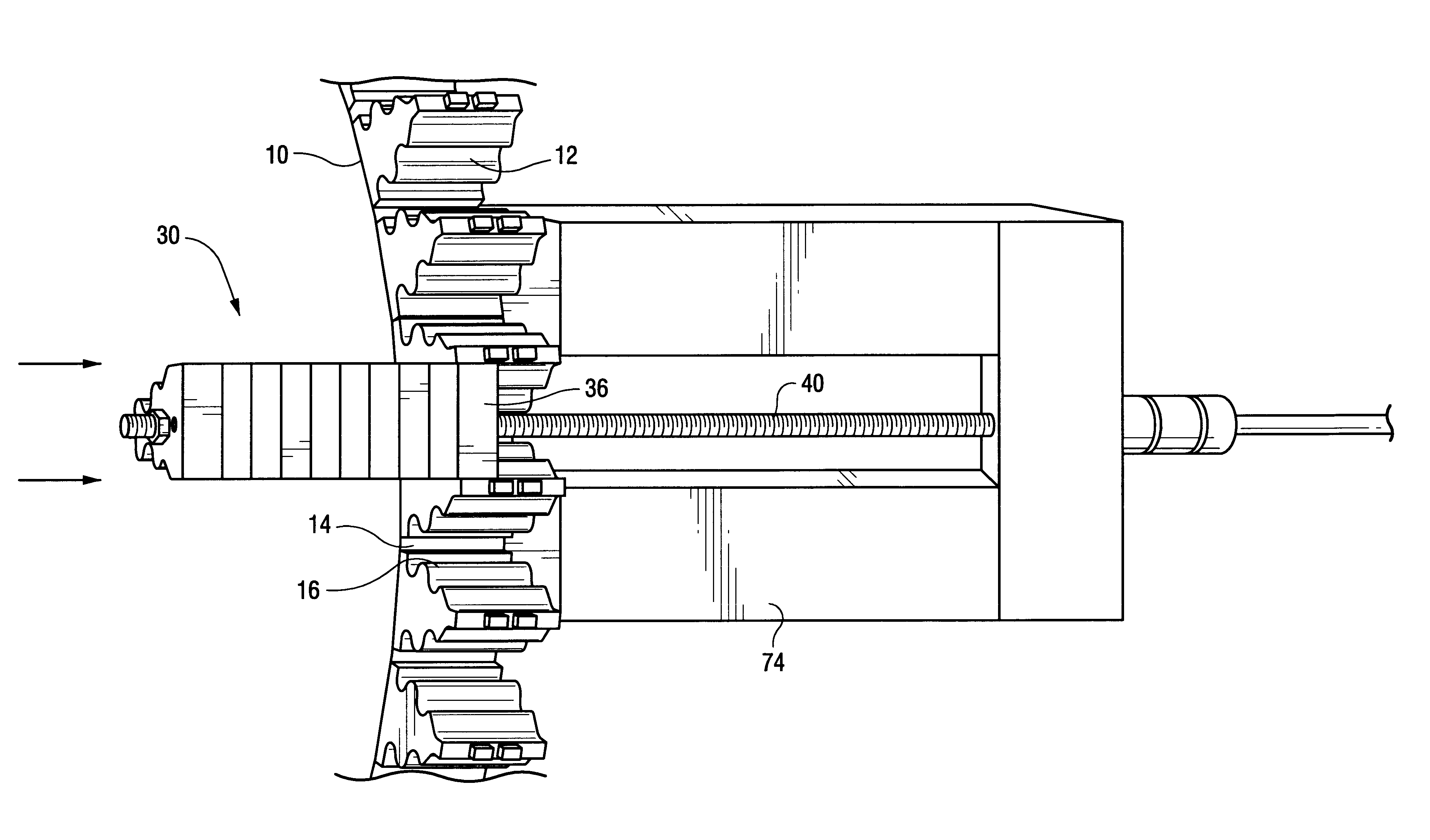
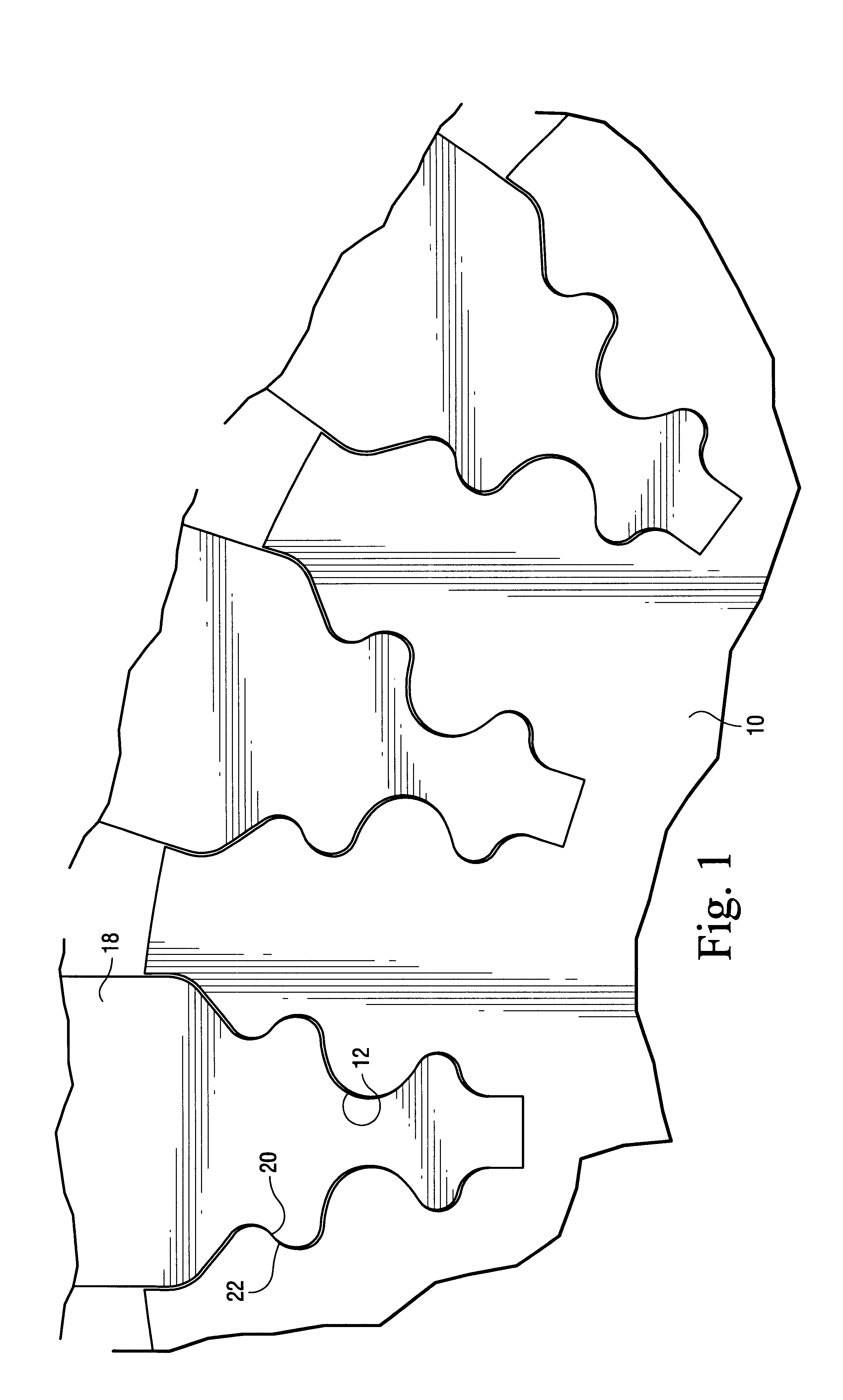
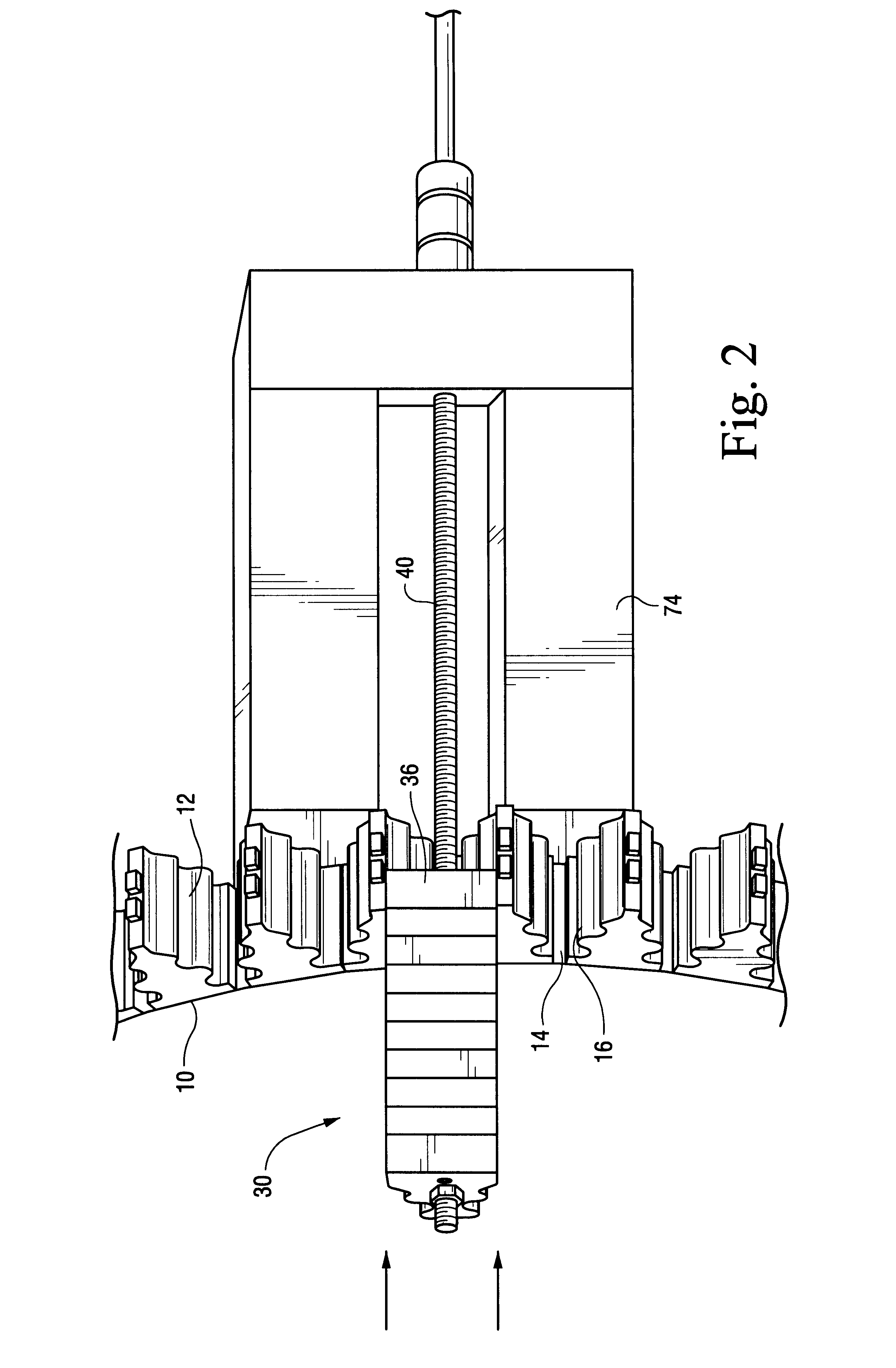
Referring now to the drawing figures, particularly to FIGS. 1-3, there is illustrated a wheel 10 forming one of the wheels of a gas or steam turbine and having a plurality of generally dovetail-shaped slots 12 spaced circumferentially one from the other about the peripheral margin of the wheel 10. As illustrated, each slot 12 includes a slot bottom 14 and a plurality of ribs 16 along opposite sides of the slot and progressively spaced greater distances from one another from the bottom of the slot 14 radially outwardly to its outermost opening. From a review of FIG. 1, a rotor blade or bucket 18 having a generally corresponding dovetail-shaped configuration at its root as the dovetail configuration of the slot 12 is disposed in each slot 12 about the rotor. It will be appreciated that when the rotor rotates, the outermost surfaces of the ribs 16 of the dovetail slot and those of the bucket dovetails constitute active surfaces 20 and 22, respectively, which tightly bear against one an...


PUM


Abstract

The broach assembly includes alternate spacers and cutters arranged in a sub-assembly having a lead at a leading end and a lag at a trailing end. The cutters have side margins in excess of the margins of the spacers for cutting material from the dovetail slots of the turbine wheel as the broach assembly passes through the slots. The bottom or apices of each spacer and cutter are tapered to form a continuously tapered surface along the bottom of the broach assembly. Upon passing the broach assembly through the slot, the assembly is progressively displaced in a radial outward direction to progressively cut the active dovetail slot surfaces. Shims may be disposed in the bottom of the slot to further displace the broach assembly radially outwardly in multiple passes.

Description

BACKGROUND OF THE INVENTIONThe present invention relates to a broach assembly for cutting surfaces in a slot and particularly relates to a broach assembly for use in a turbine for cutting active surfaces of dovetail slots and methods of cutting the slots.Various machined configurations used for fitting or attachment of fixed or movable parts frequently wear as a function of time and use. For example, mating dovetails are generally employed on the wheels and buckets of a turbine for securing those parts to one another. Conventionally, shapers, planers and milling machines are utilized to form the original dovetails. In a gas turbine, the wheels form separate or discrete parts which are assembled to form the rotor. Once assembled, the original tools utilized to form the dovetail slots cannot be used to repair the slots in assembly, principally due to the proximity of the wheels to one another. Similarly, the dovetail slots on the wheels of steam turbines cannot be readily repaired usi...

Claims


Application Information

Patent Timeline
IPC IPC(8): B23D43/02B23D43/00B23P6/00B23D37/00B23D37/22
CPCB23D37/22B23D43/02B23P6/002B23D2043/025Y10T407/16Y10T407/1685Y10T407/1628
Inventor NOLAN, JOHN FRANCISPOLLOCK, RALPH ARNOLDFISCHER, TODD JOSEPH
Owner GENERAL ELECTRIC CO
Why Eureka
Try Eureka