Camera fixing jig

A technology for fixing fixtures and cameras, which is applied in the field of fixtures, can solve the problems of complicated installation and disassembly process, increase the manufacturing cost of fixtures, and not meet the actual needs, etc., and achieve simple structure, ensure reliability, and facilitate positioning and limit Effect

Pending Publication Date: 2020-02-07
长园半导体设备(珠海)有限公司
View PDF0 Cites 2 Cited by
  • Summary
  • Abstract
  • Description
  • Claims
  • Application Information

AI Technical Summary

Problems solved by technology

In the existing fixing methods, if a simple cylinder is used for fixing, the resulting problems are insufficient precision or unstable clamping
If a complex fixture is used to position and clamp the camera, for example, bolts and other parts need to be screwed during the installation and disassembly process, it will not only lead to complicated installation and disassembly process, but also greatly increase the manufacturing cost of the fixture, which does not meet the actual needs

Method used


Image

  • Camera fixing jig
  • Camera fixing jig
  • Camera fixing jig

Examples


Embodiment Construction

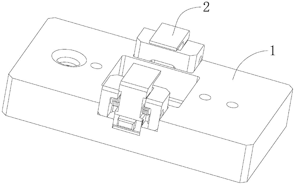
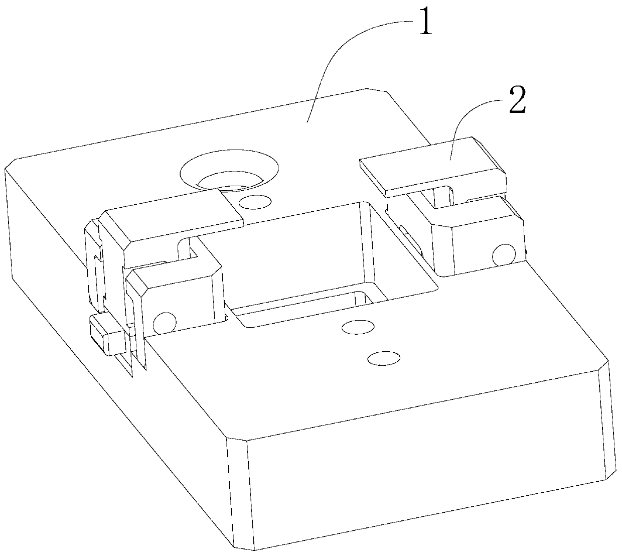
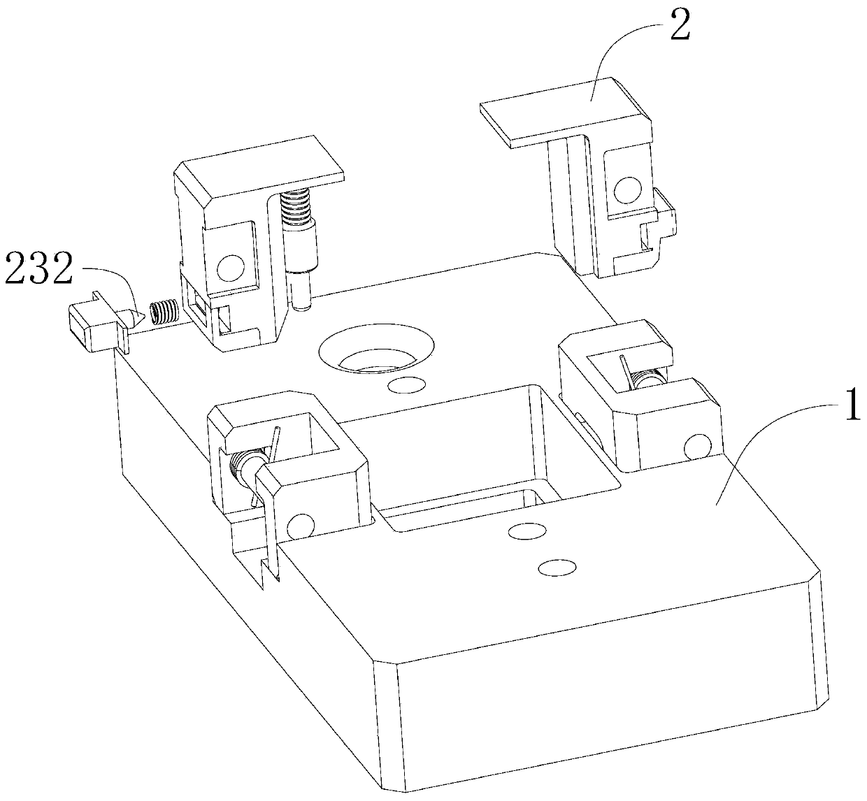
[0032] Below, the present invention will be further described in conjunction with the accompanying drawings and specific implementation methods. It should be noted that, under the premise of not conflicting, the various embodiments described below or the technical features can be combined arbitrarily to form new embodiments. .

[0033] In describing the present invention, it is to be understood that the terms "upper", "lower", "front", "rear", "left", "right", "horizontal", "vertical", "top", The orientation or positional relationship indicated by "inner", "outer", etc. is based on the orientation or positional relationship shown in the drawings, and is only for the convenience of describing the present invention and simplifying the description, rather than indicating or implying that the referred device or element must have Certain orientations, constructed and operative in certain orientations, therefore are not to be construed as limitations of the invention. In addition, ...


PUM


Abstract

The invention discloses a camera fixing jig comprising a jig body, rotating claws, torsion springs, locking rods and first elastic pieces. The jig body is provided with a locating hole used for containing a camera. The jig body is further provided with limiting holes spaced from the locating hole at a certain distance. The axis of the locating hole is parallel to the axis of each limiting hole. The rotating claws are connected to the jig body in a pivoted manner. The two ends of each torsion spring abut against the jig body and the corresponding rotating claw in a connection manner correspondingly. Each torsion spring is used for driving the corresponding rotating claw to limit the camera into the locating hole. The locking rods are movably connected with the rotating claws in a sleeved manner, so that the locking rods can move in the length direction of the locking rods. The two ends of each first elastic piece are connected with the jig body and the corresponding rotating claw correspondingly. The first elastic pieces are used for driving the locking rods to be inserted into the limiting holes. The camera fixing jig is simple in structure, capable of conveniently clamp the cameraand low in manufacturing cost.

Description

technical field [0001] The invention relates to the technical field of jigs, in particular to a jig for fixing a camera. Background technique [0002] When producing a camera or testing the machining accuracy and performance of the camera, the camera needs to be positioned and fixed to ensure the machining accuracy or the accuracy of the testing result. In the existing fixing methods, if a simple air cylinder is used for fixing, the problems caused by this are insufficient precision or unstable clamping. If a complex fixture is used to position and clamp the camera, for example, parts such as bolts need to be screwed during the installation and disassembly process, it will not only lead to complicated installation and disassembly processes, but also greatly increase the manufacturing cost of the fixture, which does not meet actual needs. [0003] Therefore, it is of great significance to design a camera fixture that is simple in structure, convenient for clamping the camera...

Claims


Application Information

Patent Timeline
Patent Type & Authority Applications(China)
IPC IPC(8): B25B11/00
CPCB25B11/00
Inventor 侯峰
Owner 长园半导体设备(珠海)有限公司
Why Eureka
Try Eureka