High-pressure unloading type gunpowder gas-actuated valve

A gas and gunpowder technology, applied in the field of high-pressure unloading gunpowder gas actuating valves, can solve the problems of high production cost, unreliable wedging positioning, and inability to handle chips in time, and achieves high adaptability, reliable positioning, and tight wedging. solid effect

Active Publication Date: 2020-02-07
XIAN AEROSPACE PROPULSION INST
View PDF6 Cites 2 Cited by
  • Summary
  • Abstract
  • Description
  • Claims
  • Application Information

AI Technical Summary

Benefits of technology

This patented technology allows for better control over firearms powders when they use them under different conditions such as extreme temperatures or atmospheric pollution levels. It also includes improvements like improved safety features due to increased stability at elevated temperatures and reduced risk from accidentally igniting flammable materials stored within it. Additionally, this design provides greater flexibility than previous designs where there was only one set of structure being used instead of each other. Overall, these technical benefits improve performance and reliance of firearm systems while maintaining their effectiveness against environmental factors.

Problems solved by technology

This patented technical problem addressed in this patents relates to improving the performance and lifespan of an electronic exploding (EES)-based weapon's powertrain valve due to factors such as poor electrical conductivity or insulation caused by residual particles from previous designs. Additionally, current methods like punch riveting often result in excessive chip generation which negatively impact product functionality.

Method used


Image

  • High-pressure unloading type gunpowder gas-actuated valve
  • High-pressure unloading type gunpowder gas-actuated valve
  • High-pressure unloading type gunpowder gas-actuated valve

Examples


Embodiment Construction

[0041] In order to make the purpose, advantages and features of the present invention more clear, a high-pressure unloading gunpowder gas actuated valve proposed by the present invention will be further described in detail below in conjunction with the accompanying drawings and specific embodiments. The advantages and features of the present invention will be more clear from the following specific embodiments. It should be noted that: the drawings are all in a very simplified form and use inaccurate proportions, which are only used to facilitate and clearly illustrate the purpose of the embodiments of the present invention; secondly, the structures shown in the drawings are often actual structures part.

[0042] The present invention will be described in detail below in conjunction with the accompanying drawings and specific embodiments.

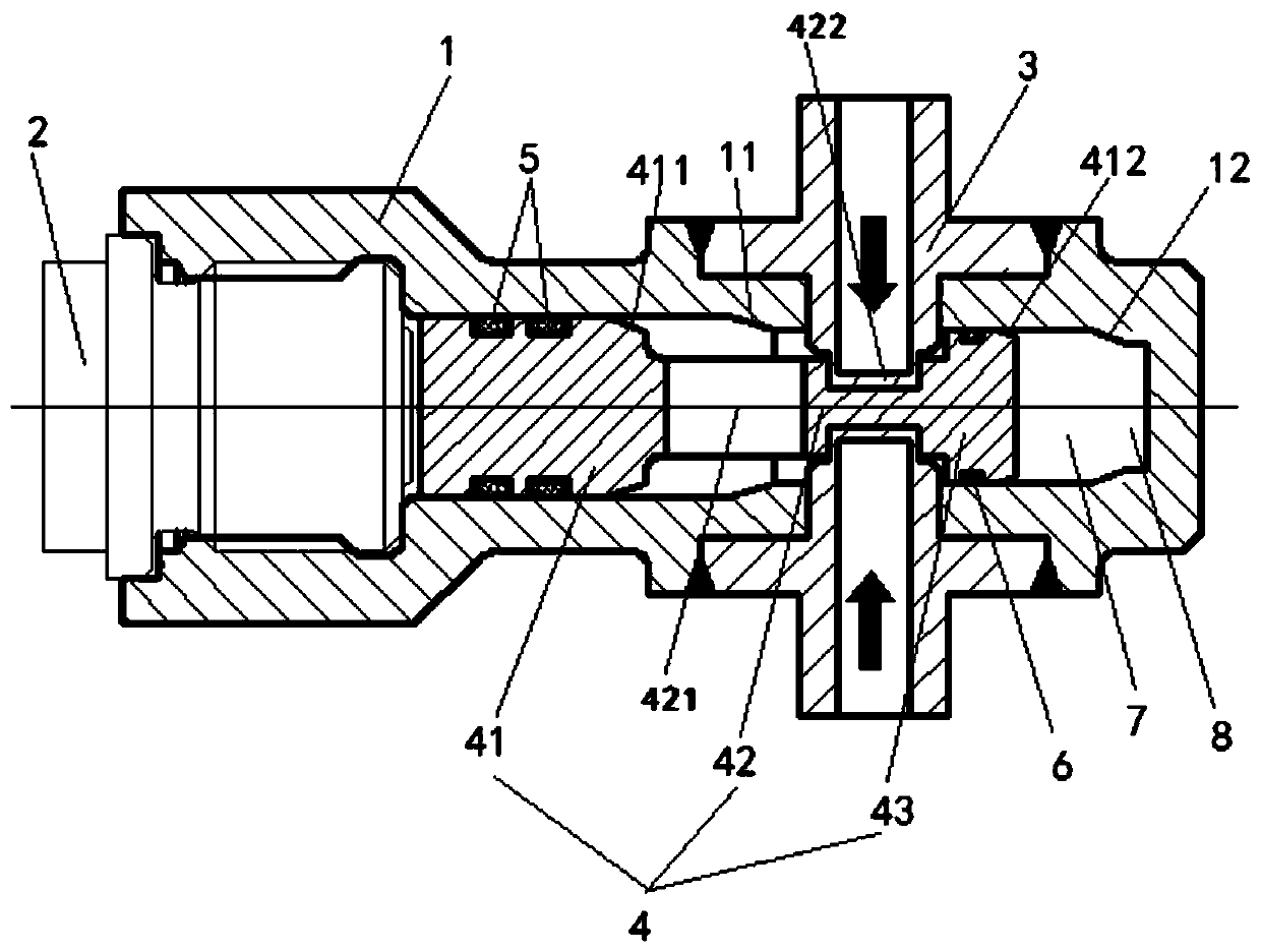
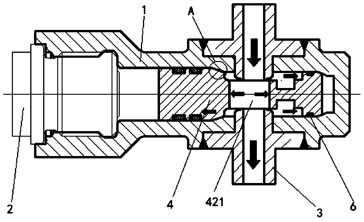
[0043] The present invention is a high-pressure unloading type gunpowder gas actuated valve, which combines figure 1 , figure 2 As show...


PUM


Abstract

The invention relates to a high-pressure unloading type gunpowder gas-actuated valve, and aims to solve the problems that an electric explosion valve in the prior art can only be used in a certain pressure range, chips cannot be timely disposed, the production cost is high, and wedging and positioning are not firm. The gas-actuated valve comprises an electric explosion tube, a base body, blind tubes and a cutter assembly. The electric explosion tube is installed at the left end of the base body, the two blind pipes are symmetrically installed at the right end of the base body in the circumferential direction, and the cutter assembly is mounted in the base body. The cutter assembly comprises a large-diameter driving section, a small-diameter cutting section and a small-diameter unloading section which are sequentially connected from left to right. A gas firestop sealing ring is arranged between the outer wall of the large-diameter driving section and the inner wall of the base body. A flow passing hole is formed in the left portion of the small-diameter cutting section. Two symmetrical grooves are formed in the right portion of the small-diameter cutting section. An unloading sealing ring is arranged between the small-diameter unloading section and the base body. The closed ends of the blind pipes penetrate through the base body and are matched with the grooves. A cavity capableof containing the small-diameter cutting section and a cavity for wedging the cutter assembly and the base body are sequentially formed in the portion, on the right side of the cutter assembly, in the base body.

Description


Claims


Application Information

Patent Timeline
Owner XIAN AEROSPACE PROPULSION INST
Why Eureka
Try Eureka