
Drilling fluid detection equipment

A technology for detecting equipment and drilling fluid, which is applied in the field of oil exploration experimental equipment, and can solve problems such as excessive drilling fluid pressure and difficulty in accurately determining drilling fluid pressure

Active Publication Date: 2020-02-07
PETROCHINA CO LTD
View PDF8 Cites 0 Cited by
  • Summary
  • Abstract
  • Description
  • Claims
  • Application Information

AI Technical Summary

Problems solved by technology

[0005] In view of this, the present invention provides a drilling fluid detection device to solve the technical problems in the prior art that it is difficult to accurately determine the pressure of the drilling fluid, and it is easy to cause the pressure of the drilling fluid to be too high or too low

Method used


Image

  • Drilling fluid detection equipment
  • Drilling fluid detection equipment
  • Drilling fluid detection equipment

Examples


Embodiment Construction

[0049] In order to make the purpose, technical solutions and advantages of the embodiments of the present invention clearer, the technical solutions in the embodiments of the present invention will be clearly and completely described below in conjunction with the drawings in the embodiments of the present invention. Obviously, the described embodiments It is a part of embodiments of the present invention, but not all embodiments. Based on the embodiments of the present invention, all other embodiments obtained by persons of ordinary skill in the art without creative efforts fall within the protection scope of the present invention.

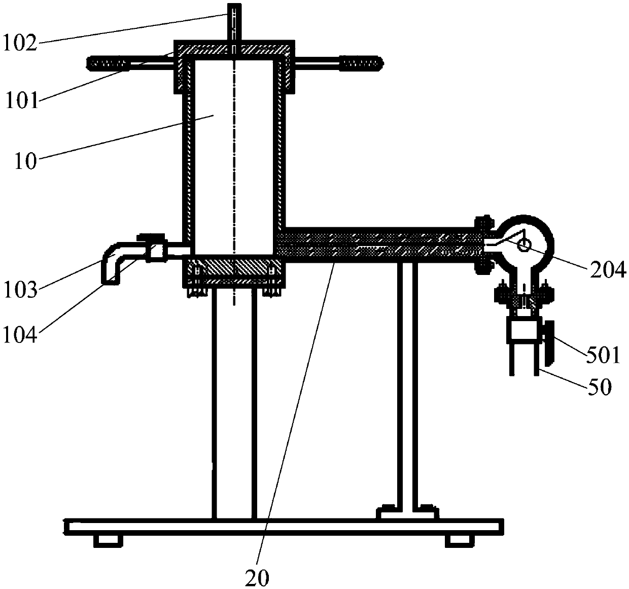
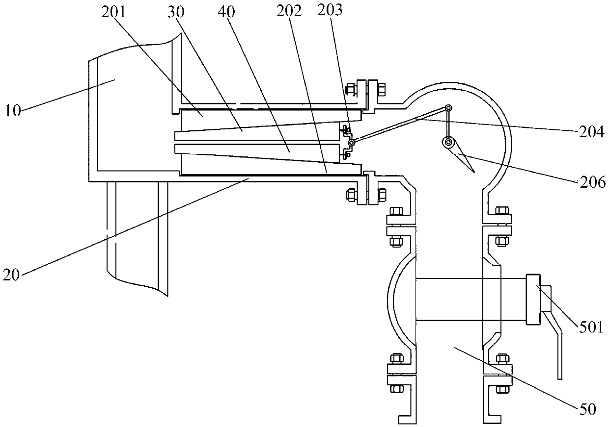
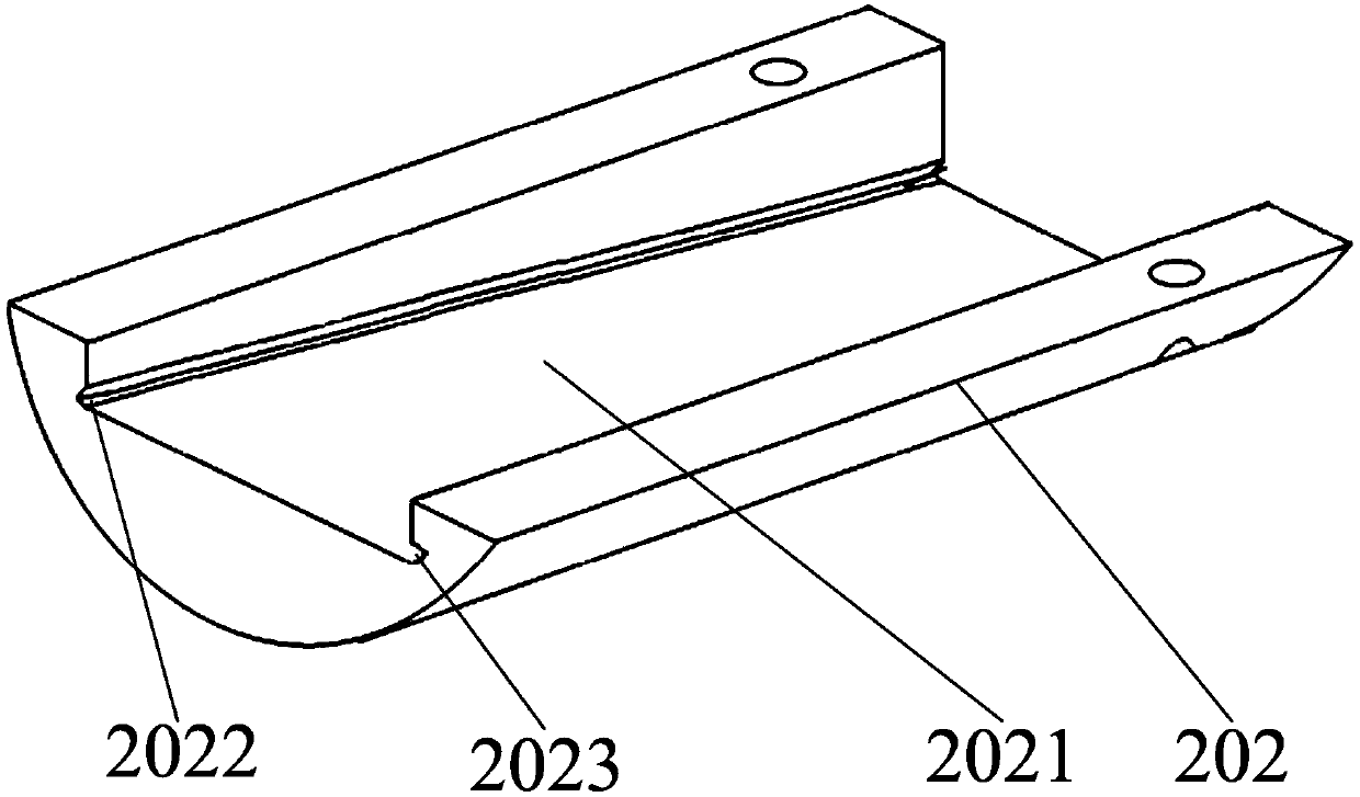
[0050] figure 1 Schematic diagram of the structure of the drilling fluid detection equipment provided by the embodiment of the present invention; figure 2 A schematic diagram of the internal structure of the drilling fluid detection equipment provided by the embodiment of the present invention; image 3 for figure 2Schematic diagram of the st...


PUM


Abstract

The invention provides drilling fluid detection equipment. The drilling fluid detection equipment comprises a storage barrel, a sliding pipe, a first sliding block, a second sliding block, a stop spring and a detection device; a first inclined surface is arranged on one side, facing the second limiting block, of the first limiting block; a second inclined surface is arranged on one side, facing the first limiting block, of the second limiting block; the first sliding block and the second sliding block are both arranged in the sliding pipe. The detection device is connected with the rear ends of the first sliding block and the second sliding block so as to detect the backward movement distance of the first sliding block and the second sliding block; drilling fluid with different pressures is injected into the storage barrel; different actual distances between the first sliding block and the second sliding block are calculated according to the backward movement distances, obtained by thedetection device, of the first sliding block and the second sliding block; the drilling fluid pressure corresponding to the actual distance close to the actual width of an underground rock stratum crack is selected as the pressure of the drilling fluid during actual drilling; the pressure of the drilling fluid can be accurately determined, and the situation that the pressure of the drilling fluidis too large or too small is avoided.

Description

technical field [0001] The invention relates to the technical field of oil exploration experimental equipment, in particular to drilling fluid testing equipment. Background technique [0002] In the process of oil extraction, it is necessary to drill the well pipe underground first, and the well pipe extends underground to the oil reservoir; during the drilling process, the drill bit will damage the underground rock formation, and then form cracks on the rock formation, so that the drilling fluid flows into the crack The flow causes the loss of drilling fluid; therefore, how to seal the fractures on the rock formation to avoid the loss of drilling fluid has become a research hotspot. [0003] In the prior art, the drilling fluid is often mixed with appropriate particles to seal the cracks on the rock formation; wherein the particles are sand or stones with a certain particle size. When the drill bit rotates to drill the well pipe underground, the drilling fluid with a certa...

Claims


Application Information

Patent Timeline
IPC IPC(8): G01N33/26
CPCG01N33/26
Inventor 尹达蒲晓林李宁李磊李家学贾红军黄超王攀张玮冯伟雄吴晓花张绍俊王涛王慧冯惠李卫东
Owner PETROCHINA CO LTD
Learn More