
Method of readjusting a pressure sensor in an engine air intake line, as a function of temperature

A technology of pressure sensor and calibration method, which is applied in the direction of engine control, machine/engine, electrical control, etc., to achieve the effect of cost saving

Inactive Publication Date: 2018-09-04
PEZHO SITROEN AUTOMOBILS SA
View PDF6 Cites 2 Cited by
  • Summary
  • Abstract
  • Description
  • Claims
  • Application Information

AI Technical Summary

Problems solved by technology

This system does not solve the problem of calibrating the same pressure sensor against temperature

Method used


Image

  • Method of readjusting a pressure sensor in an engine air intake line, as a function of temperature
  • Method of readjusting a pressure sensor in an engine air intake line, as a function of temperature

Examples


Embodiment Construction

[0053] figure 1 It has been described in the introductory part of the present invention.

[0054] refer to figure 2 , shows a logic diagram of the calibration method for at least three sensors, namely barometric pressure sensor, boost sensor and intake sensor air. These pressure sensors may all be present in the intake line of the internal combustion engine, which is advantageously a spark ignition engine.

[0055] The boost sensor may be located downstream of a turbocharger compressor of the internal combustion engine, and the intake sensor may be located in an air distributor inlet of the internal combustion engine.

[0056] However, as previously stated, it should be noted that the invention can be applied to only one pressure sensor or to a different number of pressure sensors than three, for example not using a boost sensor when the engine is not a turbocharger. Likewise, other pressure sensors than the aforementioned sensors may be considered.

[0057] In the case o...


PUM


Abstract

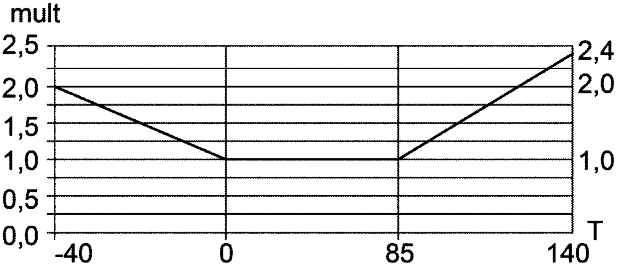
The invention relates to a method for readjusting at least one pressure sensor positioned in an internal combustion engine air intake line by applying a temperature-dependent correction factor so thatthe sensor can measure pressure with respect to the true atmospheric pressure using the equation Px = P + Fx, the factor Fx being given by Fx = exref.multx(T), exref being the reference error of thepressure sensor and multx(T) being an error multiplier at a temperature T. The reference error inherent to the sensor is calculated by two pressure measurements by the pressure sensor at two differenttemperatures (T1, T2), one of them with the engine stopped, the factor Fx and, therefore, the sensor measurement Px, being readjusted as a function of the reference error inherent to the sensor. Thepressure sensor may be an atmospheric sensor, boost-pressure sensor or air intake sensor.

Description

technical field [0001] The invention relates to a method for temperature-dependent calibration of at least one pressure sensor located in the intake line of an internal combustion engine. [0002] The invention belongs to the technical field of the control system of the internal combustion engine, and the internal combustion engine is preferably a spark ignition type. Background technique [0003] There are usually three pressure sensors in the intake line of an internal combustion engine, namely the barometric pressure sensor, the boost pressure sensor and the intake pressure sensor. When the engine is a turbocharged engine, the boost pressure sensor is located downstream of the compressor of the turbocharger; the intake pressure sensor is located in the air distributor. These three sensors are used to measure the pressure at certain points in the intake line. [0004] The measurement accuracy of a pressure sensor is related to its temperature. Generally speaking, within...

Claims


Application Information

Patent Timeline
Patent Type & Authority Applications(China)
IPC IPC(8): F02D41/24
CPCF02D41/2441F02D41/2474F02D2041/1433F02D2200/0406
Inventor 菲力浦·奎伊朱利安·乐米埃珍·路易斯·沙里耶
Owner PEZHO SITROEN AUTOMOBILS SA
Learn More