A hose corner connector

A corner connector and hose technology, which is applied to hose connection devices, adjustable connections, pipes/pipe joints/pipes and other directions, can solve the problems of inconvenient disassembly, inability to adjust, and complicated installation, etc. simple structure

Active Publication Date: 2021-11-19
徐州华显凯星信息科技有限公司
View PDF6 Cites 0 Cited by
  • Summary
  • Abstract
  • Description
  • Claims
  • Application Information

AI Technical Summary

Problems solved by technology

[0002] At present, in industrial production, flexible pipes are usually used to transport liquids. In some environments, in order to facilitate the layout of pipelines, it is necessary to connect pipelines. When they rub against each other and squeeze each other, the pipeline will be cracked and leaked under pressure, which will affect the transmission of the pipeline, and then it is necessary to protect the corner connection position of the pipeline. Some existing corner protections are mainly to put protective sleeves on the outside of the pipeline, or use metal protective sleeves in the design. Hard tube, but there is still wear and tear between the protective sleeve and the pipeline. The metal hard tube only strengthens the material, and the use of metal hard tubes has a narrow range of application due to the fixed angle. However, some existing protective devices have complex structures. Protective structures such as brackets are installed on the outside of the pipeline, which takes up a lot of space, is complicated to install, and is inconvenient to disassemble
[0003] Publication No. CN207431449U discloses a copper pipe quick-connect pipe fitting, which includes a base pipe on which a welding device that can weld the base pipe and the pipe fitting to be inserted is provided. The device mainly uses plug-in connection, but due to It's made of copper so it can't be turned, the applicable corners are fixed and can't be adjusted

Method used


Image

  • A hose corner connector
  • A hose corner connector
  • A hose corner connector

Examples


Embodiment Construction

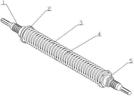
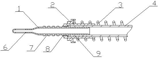
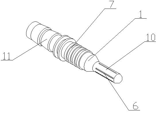
[0018] A hose corner connector of the present invention is realized in this way, consisting of a connecting nozzle 1, a screw sleeve 2, a spring 3, a middle connecting pipe 4, a fixing sleeve 5, a communication groove 6, a fastening protrusion 7, and a limit snap ring 8 , an inner fixing ring 9, an introduction nozzle 10 and a tower-shaped connector 11, two fixing sleeves 5 are respectively placed on the outer walls of the two ends of the middle connecting pipe 4, the middle connecting pipe 4 is a rubber tube, and the fixing sleeve 5. There is a through hole in the middle of one end, and one end of the two connecting nozzles 1 is placed in the two ends of the middle connecting pipe 4 respectively, and the other ends of the two connecting nozzles 1 pass through the through holes on the two fixing sleeves 5 respectively. Note that a limit snap ring 8 is placed on the outer wall of the connecting nozzle 1, and is clamped on one end of the fixed sleeve 5, and a plurality of conical...


PUM


Abstract

The invention discloses a hose corner connector that is easy to install, connects hoses at different corners through a soft middle connecting pipe, and wraps and protects the middle connecting pipe through a spring to avoid wear and tear on the corner position. device. It can protect and support the corner position and improve the connection strength of the pipeline. It is characterized in that the two fixing sleeves are respectively placed on the outer walls of the two ends of the middle connecting pipe, the middle connecting pipe is a rubber tube, a through hole is opened in the middle of one end of the fixing sleeve, and one end of the two connecting nozzles is respectively placed on the In the two ends of the middle connecting pipe, the other ends of the two connecting nozzles pass through the through holes on the two fixing sleeves respectively, and the outer wall of the connecting nozzles is provided with a limit snap ring, which is locked in the fixing sleeves. On one end, a plurality of conical trusses are equidistantly arranged on the outer surface of the connecting nozzle to form a tower-shaped connecting head, and the tower-shaped connecting head is located in the middle connecting pipe.

Description

technical field [0001] The invention relates to a hose corner connector, which relates to a connector with a protective structure for connecting the corner of a hose, and belongs to the field of industrial equipment. In particular, it relates to a corner connector that is easy to install, connects hoses at different corners through a flexible middle connecting pipe, and wraps and protects the middle connecting pipe through a spring to avoid wear at the corner. Background technique [0002] At present, in industrial production, flexible pipes are usually used to transport liquids. In some environments, in order to facilitate the layout of pipelines, it is necessary to connect pipelines. When they rub against each other and squeeze each other, the pipeline will be cracked and leaked under pressure, which will affect the transmission of the pipeline, and then it is necessary to protect the corner connection position of the pipeline. Some existing corner protections are mainly t...

Claims


Application Information

Patent Timeline
Patent Type & Authority Patents(China)
IPC IPC(8): F16L27/107F16L33/24F16L57/06
CPCF16L27/107F16L33/24F16L57/06
Inventor 不公告发明人
Owner 徐州华显凯星信息科技有限公司
Why Eureka
Try Eureka