
Radial offset monitoring and alarming device for cylindrical equipment

A technology of monitoring and alarming devices and alarming devices, which is applied in the direction of measuring devices, optical devices, instruments, etc., can solve problems such as damage, equipment instability damage, accidents, etc., and achieve the effect of wide applicability and sensitive response

Active Publication Date: 2020-02-11
LIAONING TECHNICAL UNIVERSITY
View PDF11 Cites 3 Cited by
  • Summary
  • Abstract
  • Description
  • Claims
  • Application Information

AI Technical Summary

Problems solved by technology

[0002] At present, most load-bearing structures or mechanical transmission shafts are cylinders, such as static bridge piers, building pressure columns, etc., which usually bear huge loads. When they are subjected to horizontal forces or the foundation is not stable, it is easy to occur. Deviation, after deflection, the equipment will be in an abnormal stress state. If the deviation is not detected in time and corrective measures are taken, the deviation will continue to develop and deteriorate, eventually leading to equipment instability and damage
As for equipment in a rotating state, such as various mechanical shafts, etc., such equipment must bear certain torque and impact during operation, and at the same time perform rotational motion. When the axis line deviates, the transmission parts will be released and incompletely meshed. , prone to wear, deformation and damage, resulting in reduced transmission efficiency and even accidents

Method used


Image

  • Radial offset monitoring and alarming device for cylindrical equipment
  • Radial offset monitoring and alarming device for cylindrical equipment
  • Radial offset monitoring and alarming device for cylindrical equipment

Examples


Embodiment Construction

[0018] The following will clearly and completely describe the technical solutions in the embodiments of the present invention with reference to the accompanying drawings in the embodiments of the present invention. Obviously, the described embodiments are only some, not all, embodiments of the present invention. Based on the embodiments of the present invention, all other embodiments obtained by persons of ordinary skill in the art without making creative efforts belong to the protection scope of the present invention.

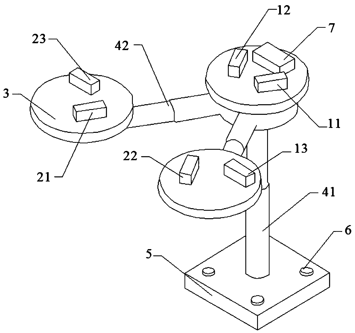
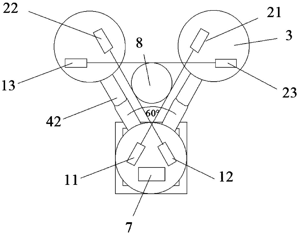
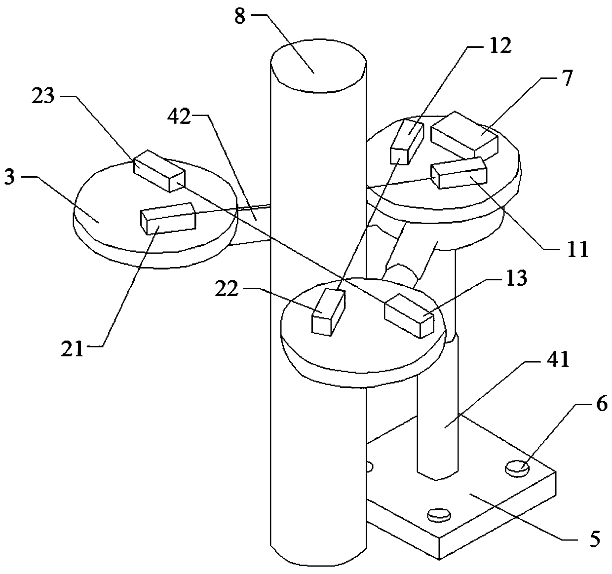
[0019] The purpose of the present invention is to provide a radial displacement monitoring and alarming device for cylindrical equipment to solve the above-mentioned problems in the prior art and realize real-time monitoring and alarming of the radial displacement of static or dynamic cylindrical equipment.

[0020] In order to make the above objects, features and advantages of the present invention more comprehensible, the present invention will be further des...


PUM


Abstract

The invention discloses a radial offset monitoring and alarming device for cylindrical equipment. The radial offset monitoring and alarming device comprises a base, wherein a vertical telescopic supporting rod is arranged on the base; the side wall of the top end of the vertical telescopic supporting rod is further connected with two horizontal telescopic supporting rods; the top end of the vertical telescopic supporting rod and one ends, away from the vertical telescopic supporting rod, of the two horizontal telescopic supporting rods are each connected with a supporting disc; three sets of laser correlation devices are arranged on the three supporting discs in total; each set of laser correlation devices comprises a laser emitter and a laser receiver which are arranged on different supporting discs, and the supporting discs corresponding to any two sets of laser correlation devices are different; an alarm device is arranged on one supporting disc; and the laser emitters and the laserreceivers are electrically connected with the alarm device. The radial offset monitoring and alarming device for the cylindrical equipment can perform real-time monitoring and alarm on radial offsetof the static or dynamic cylindrical equipment.

Description

technical field [0001] The invention relates to the technical field of monitoring equipment, in particular to a monitoring and alarming device for radial deviation of cylindrical equipment. Background technique [0002] At present, most load-bearing structures or mechanical transmission shafts are cylinders, such as static bridge piers, building pressure columns, etc., which usually bear huge loads. When they are subjected to horizontal forces or the foundation is not stable, it is easy to occur. Deviation, after deflection, the equipment will be in an abnormal stress state. If the deviation is not detected in time and corrective measures are taken, the deviation will continue to develop and deteriorate, eventually leading to equipment instability and damage. As for equipment in a rotating state, such as various mechanical shafts, etc., such equipment must bear certain torque and impact during operation, and at the same time perform rotational motion. When the axis line devi...

Claims


Application Information

Patent Timeline
Patent Type & Authority Applications(China)
IPC IPC(8): G01B11/02G08B3/10
CPCG01B11/02G08B3/10
Inventor 王猛高函汤国水邰才王张巧峰马慧斌
Owner LIAONING TECHNICAL UNIVERSITY
Learn More