
A high-precision optical tracking and aiming device based on corner reflectors

A corner reflector, high-precision technology, used in optics, optical components, instruments, etc., can solve problems such as low energy transmission efficiency, high weight cost, and difficulty in transformation, achieving strong versatility, reducing efficiency loss, and low cost. Effect

Active Publication Date: 2022-01-25
NAT SPACE SCI CENT CAS
View PDF0 Cites 0 Cited by
  • Summary
  • Abstract
  • Description
  • Claims
  • Application Information

AI Technical Summary

Problems solved by technology

[0003] The purpose of the present invention is to solve the problems of high weight cost, difficult transformation, low energy transmission efficiency and large divergence in the current moon night survival scheme. The present invention proposes a high-precision optical tracking and aiming system based on corner reflectors. The device, which is a high-precision optical tracking device based on a corner reflector that can be used in lunar power stations, can realize low-cost and high-efficiency moon night survival

Method used


Image

  • A high-precision optical tracking and aiming device based on corner reflectors
  • A high-precision optical tracking and aiming device based on corner reflectors
  • A high-precision optical tracking and aiming device based on corner reflectors

Examples


Embodiment 1

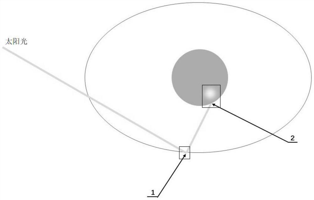
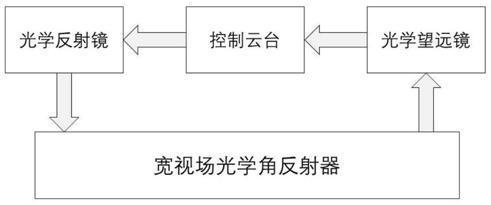
[0063] This embodiment provides a high-precision optical tracking and aiming device based on a corner reflector that can be used for a space power station on a lunar orbit. Its structure is as figure 1 As shown, it includes: an optical mirror located on the lunar orbiting space power station vehicle 1, a control platform, an optical telescope with mechanical tracking and imaging positioning functions, and a wide field of view optical corner reflector 2 located on the surface of the moon. The orbit of the lunar orbit space power station aircraft is a low-inclination large elliptical lunar orbit, with an aphelion point of 3000-4000 kilometers.

[0064] The optical reflector is controlled by the control platform, so that the positive feedback posture of the main reflector surface of the optical reflector is adjusted to ensure that it can receive the incident sunlight to the maximum, so that the overall mechanism of the optical reflector is more stable and self-contained. The abi...


PUM

PropertyMeasurementUnit
diameteraaaaaaaaaa

Abstract

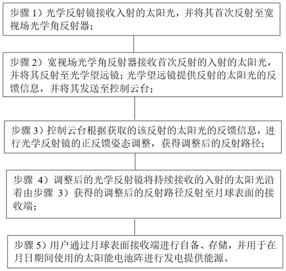
The invention belongs to the technical field of optical tracking and aiming equipment, and in particular relates to a high-precision optical tracking and aiming device based on a corner reflector. Wide field of view optical corner reflector (2); the optical reflection assembly is used to receive incident sunlight and reflect it to the wide field of view optical corner reflector (2) for the first time, and adjust the initial time according to the reflected sunlight The reflection path of the incident sunlight; then reflect the continuous incident sunlight to the optical receiving end of the moon surface along the adjusted reflection path; the wide field of view optical angle reflector (2) is used to receive the Sunlight reflected by the component and reflected back to the optically reflective component.

Description

technical field [0001] The invention belongs to the technical field of optical tracking and aiming equipment, and in particular relates to a high-precision optical tracking and aiming device based on a corner reflector. Background technique [0002] The moon is tidally locked by the earth, and its rotation period is the same as its revolution period, and a day and night are about 28 days. As long as 14 days of moon night, there is no sunlight supply on the lunar surface, and the energy supply for landing probes and future manned or unmanned bases on the lunar surface has become the main constraint factor for large-scale lunar exploration, development and utilization. In order to solve the problem of survival on a moonlit night, various technical solutions including battery energy storage, lunar soil energy storage, laser / microwave energy transmission in orbital power stations, and the use of small nuclear power plants have been proposed in the prior art. However, battery en...

Claims


Application Information

Patent Timeline
Patent Type & Authority Patents(China)
IPC IPC(8): G02B23/10G02B7/198G02B7/182
CPCG02B23/10G02B7/1821
Inventor 吴季杨震朱尧
Owner NAT SPACE SCI CENT CAS
Learn More