Wheel mounting base

A technology of mounting seat and mounting surface, which is applied in the direction of fixed grinding wheel device, grinding/polishing safety device, manufacturing tools, etc., which can solve the problem of not easy to spread the grinding surface, increased consumption of grinding abrasives, and difficult grinding chips and sufficient removal of processing heat

Active Publication Date: 2020-02-14
DISCO CORP
View PDF10 Cites 0 Cited by
  • Summary
  • Abstract
  • Description
  • Claims
  • Application Information

AI Technical Summary

Problems solved by technology

[0006] However, in this structure, since the grinding water is supplied from the supply port provided on the grinding wheel base, the grinding water is scattered around by the centrifugal force caused by the rotation of the main shaft, so it is difficult to spread over the entire grinding surface.
Therefore, it is difficult to sufficiently remove grinding dust and processing heat
Therefore, the consumption of grinding tools increases

Method used


Image

  • Wheel mounting base
  • Wheel mounting base
  • Wheel mounting base

Examples


Embodiment Construction

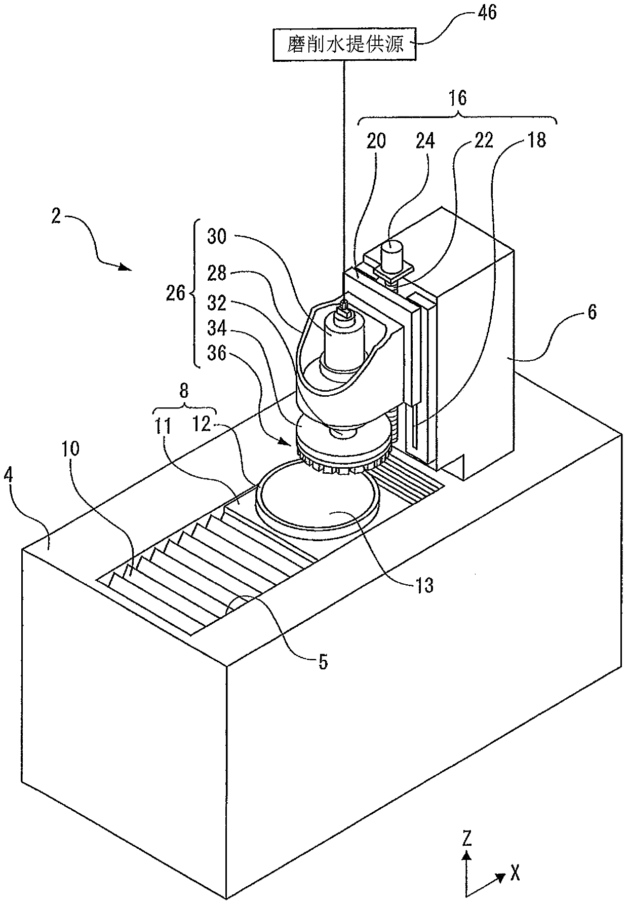
[0028] Such as figure 1 As shown, the grinding device 2 of this embodiment has: a cuboid base 4; a support column 6 extending upward; and a grinding water supply source 46 for supplying grinding water.

[0029] The front side of the upper surface of the base 4 is configured with: a chuck table portion 8 comprising a chuck table 12; an X-axis moving mechanism (not shown) that moves the chuck table portion 8 in the X-axis direction; And a waterproof cover 10 covering the X-axis moving mechanism.

[0030] The X-axis moving mechanism is provided in a rectangular opening 5 extending in the X-axis direction (front-rear direction). The X-axis moving mechanism has: a pair of X-axis guide rails parallel to the X-axis direction; an X-axis ball screw parallel to the X-axis guide rails; and a nut part connected to the X-axis ball screw and an X-axis pulse motor (not shown in the figure). Show).

[0031] An X-axis moving table 11 of the chuck table section 8 is slidably provided on the ...


PUM


Abstract

The invention provides a wheel mounting base. Even if grinding water is influenced by a centrifugal force, the grinding water can also be provided to a ground surface and a grinding surface of a grinding tool, and the loss of the grinding tool is reduced. In the wheel mounting base (34), by switching provided plugging bolts (61,63), the energy and falling position of ejected grinding water can bechanged. According to the rotation speed of the wheel mounting base (34), the ejection part can be changed, and the energy and falling position of the grinding water can be close to a proper range. Alarge amount of grinding water is provided to a space between a ground surface (1a) and a grinding tool (40). The grinding tool (40) can be well cooled, and the grinding chips can be well removed. Thewear of the grinding tool (40) can be reduced.

Description

technical field [0001] The present invention relates to wheel mounts. Background technique [0002] In a grinding apparatus for grinding a plate-shaped workpiece, as disclosed in Patent Documents 1 and 2, for example, a grinding wheel having grinding stones arranged in a ring shape is attached to a wheel mounting seat at the front end of a spindle. The plate-shaped workpiece is ground by bringing a grinding wheel rotating together with the spindle into contact with the plate-shaped workpiece held by the holding table. Grinding water is supplied to the inner peripheral surface of the grinding wheel in order to remove grinding chips and heat from grinding. [0003] Patent Document 1: Japanese Patent Application Laid-Open No. 7-223152 [0004] Patent Document 2: Japanese Patent Laid-Open No. 2015-196226 [0005] In order to supply the grinding water to the inner peripheral surface of the grinding stone as described above, a nozzle for spraying grinding water may be arranged ...

Claims


Application Information

Patent Timeline
Patent Type & Authority Applications(China)
IPC IPC(8): B24B7/22B24B55/03B24B45/00
CPCB24B7/228B24B55/03B24B45/00B24B45/003Y02P70/10B24B55/02B24B7/04H01L21/304
Inventor 阿部裕树
Owner DISCO CORP
Why Eureka
Try Eureka