Design method of water-cooled tube plate type heat exchanger

A technology of plate heat exchanger and design method, which is applied in indirect heat exchangers, design optimization/simulation, lighting and heating equipment, etc. problems, to achieve the effect of reducing the flow dead zone, large temperature difference, and strong cooling capacity

Active Publication Date: 2020-02-14
SHANDONG UNIV
View PDF10 Cites 2 Cited by
  • Summary
  • Abstract
  • Description
  • Claims
  • Application Information

AI Technical Summary

Problems solved by technology

However, this design cannot only consider the heat dissipation effect, but also from the perspective of system economy, try to avoid the situation where the pressure drop increases sharply after adding fins and the heat dissipation improvement effect is minimal

Method used


Image

  • Design method of water-cooled tube plate type heat exchanger
  • Design method of water-cooled tube plate type heat exchanger
  • Design method of water-cooled tube plate type heat exchanger

Examples


Embodiment Construction

[0040] The present disclosure will be further described below in conjunction with the accompanying drawings and specific embodiments.

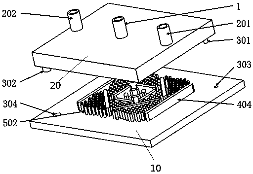
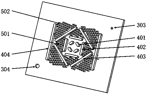
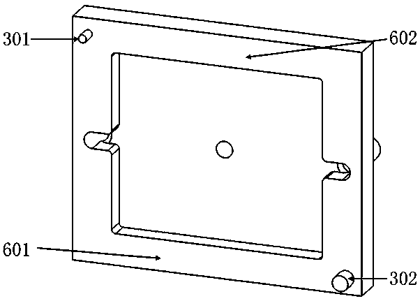
[0041] Such as Figure 1-3 The shown water-cooled plate heat exchanger includes a base plate 10 and a cover plate 20, the cover plate 20 and the base plate 10 are assembled together to form a cavity, and a cooling fluid (preferably water) flows in the cavity, and the base plate 10 is provided with The baffles 401-404 and cylindrical ribs 501, 502, the baffles include a first baffle 401 located at the center of the substrate, a second baffle 402 surrounding the first baffle 401, and a second baffle surrounded by the second baffle The third baffle 403 outside 402;

[0042] As preferred, such as Figure 1-2As shown, the first baffle plate 401 includes four pieces, and intervals are set between adjacent first baffle plates 401, and there is a vertical relationship between adjacent first baffle plates 401, and the extension lines of the four firs...


PUM


Abstract

The invention provides a design method of a water-cooled tube plate type heat exchanger. The heat exchanger comprises a base plate and a cover plate, the cover pate and the base plate are assembled together to form a fluid space, the base plate is provided with baffles and cylindrical fins, the baffles comprise the first baffle located at the center of the base plate, the second baffle surroundingthe first baffle and the third baffle surrounding the second baffle, and a nusselt number and other formulas are designed through parameters. According to the design method, through a large number ofresearches, the structure of the heat exchanger is simulated, the nusselt number and other formulas of the structure are determined for the first time, and the heat dispersion performance and pump power consumption of a water-cooled plate can be estimated by the formulas.

Description

technical field [0001] The invention relates to the technical field of heat exchangers, in particular to a plate heat exchanger with a flow guide structure combined with column ribs. Background technique [0002] The plate heat exchanger is the heat exchanger with the highest heat exchange efficiency among all kinds of heat exchangers at present. It has the advantages of small space occupation and convenient installation and disassembly. It is composed of concave-convex stainless steel plates formed by stamping. The concave-convex lines between the two adjacent plates are combined at 180 degrees. Therefore, the concave-convex ridges between the two plates of the plate heat exchanger form staggered contact points, and the contact points After being combined by vacuum welding, the high-pressure resistant staggered flow structure of the plate heat exchanger is formed. These staggered flow structures make the cold and hot fluids in the plate heat exchanger generate strong turbul...

Claims


Application Information

Patent Timeline
Patent Type & Authority Applications(China)
IPC IPC(8): F28D21/00G06F30/20
CPCF28D21/0015
Inventor 蔡伟赵夷非段晓辉张瀛瀚刘昱崔峥王宏标陈帆余道广李圣铠
Owner SHANDONG UNIV
Why Eureka
Try Eureka