Display panel and method for driving same
A display panel and driver technology, applied to static indicators, instruments, electrical components, etc., can solve problems such as poor display, and achieve the effect of preventing poor movement
- Summary
- Abstract
- Description
- Claims
- Application Information
AI Technical Summary
Problems solved by technology
Method used
Image

Examples
no. 1 approach
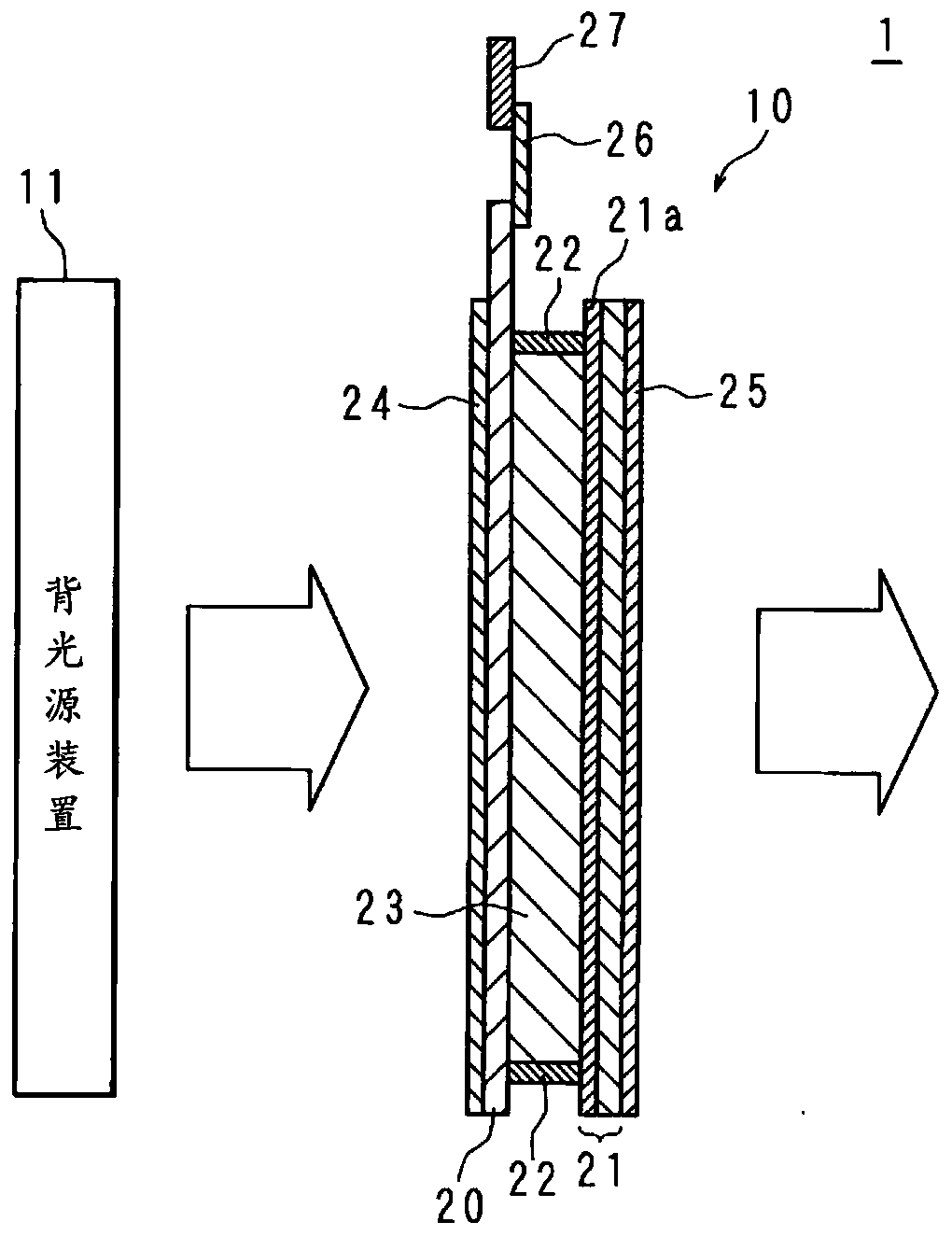
[0034] figure 1 It is a schematic diagram of the display device 1 in the first embodiment. The display device 1 includes a display panel 10 and a backlight device 11 . exist figure 1 A longitudinal section of the display panel 10 is shown in FIG. The backlight device 11 irradiates the display panel 10 with light. The display panel 10 displays an image using the light irradiated by the backlight device 11 .
[0035] The display panel 10 includes: a TFT substrate 20 ; a color filter substrate (hereinafter referred to as a “CF substrate”) 21 arranged on the front side of the TFT substrate 20 ; and a liquid crystal layer arranged between the TFT substrate 20 and the CF substrate 21 twenty three. The sealing portion 22 bonds the TFT substrate 20 and the CF substrate 21 to each other, and seals the liquid crystal layer 23 . The plurality of pixel electrodes (not shown) included in the TFT substrate 20 and the common electrode 21 a included in the CF substrate 21 are arranged t...
no. 2 approach
[0094] Figure 7 It is a flowchart showing the procedure of protection processing in the second embodiment.
[0095] Hereinafter, the difference from the first embodiment will be described with respect to the second embodiment. Since the structure other than the structure mentioned later is the same as that of the first embodiment, the same components as those of the first embodiment are given the same reference numerals as those of the first embodiment, and the description thereof will be omitted.
[0096] The display device 1 in the second embodiment differs from the display device 1 in the first embodiment in that the protection processing executed by the control unit 70 of the control circuit 50 included in the display panel 10 is different.
[0097] Like the first embodiment, the control unit 70 periodically executes the protection process in the second embodiment. Steps S21 to S23 and S27 to S29 of the protection process in the second embodiment are the same as steps S...
no. 3 approach
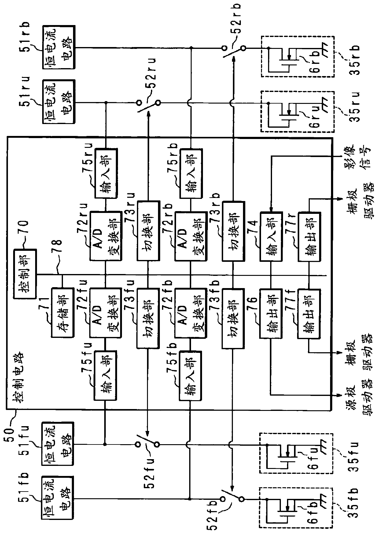
[0106] Figure 8 It is an explanatory diagram of the control circuit 50 and the monitoring circuits 35ru, 35rb, 35fu, and 35fb in the third embodiment.
[0107] Hereinafter, the difference from the first embodiment will be described with respect to the third embodiment. Since the structure other than the structure mentioned later is the same as that of the first embodiment, the same components as those of the first embodiment are given the same reference numerals as those of the first embodiment, and the description thereof will be omitted.
[0108] In the third embodiment, the temperature difference detection circuit is based on the drain current of the first TFT and the second TFT when a predetermined DC voltage is supplied to the gates of the first TFT and the second TFT formed close to the driver. of the drain current, while detecting the difference between the temperature of the first TFT and the temperature of the second TFT.
[0109] The display panel 10 in the third ...
PUM
 Abstract
Description
Claims
Application Information
 - R&D Engineer
- R&D Manager
- IP Professional
- Industry Leading Data Capabilities
- Powerful AI technology
- Patent DNA Extraction
Browse by: Latest US Patents, China's latest patents, Technical Efficacy Thesaurus, Application Domain, Technology Topic.
© 2024 PatSnap. All rights reserved.Legal|Privacy policy|Modern Slavery Act Transparency Statement|Sitemap