Separate type submersible pressure hull clamp automatic locking device and submersible pressure hull adopting the locking device

An automatic locking, submersible technology, used in transportation and packaging, underwater operation equipment, ships, etc., can solve the problem that the clamp and the pressure hull cannot be in close contact, increase the separation of the pressure hull and enter the water, and deep-sea personal safety. Threats and other issues, to achieve the effect of reducing processing and installation accuracy requirements, simple structure, and beneficial to modular manufacturing

Active Publication Date: 2019-02-15
SHANGHAI OCEAN UNIV +1
View PDF5 Cites 0 Cited by
  • Summary
  • Abstract
  • Description
  • Claims
  • Application Information

AI Technical Summary

Problems solved by technology

For the pressure hull of the submersible, the first layer of seal is slightly thin. Once the seal fails, it will pose a great threat to personal safety in the deep sea; A certain amount of deformation will occur, and the clamp retains its original shape due to seawater pressure inside and outside, and the screw locking device cannot re-lock the clamp, so that the clamp and the pressure shell cannot be tightly contacted. , which increases the possibility of separation of the upper and lower hemisphere pressure hulls and water ingress, which will cause damage to the equipment in it, especially when manned, it will be very dangerous for deep-sea operators

Method used


Image

  • Separate type submersible pressure hull clamp automatic locking device and submersible pressure hull adopting the locking device
  • Separate type submersible pressure hull clamp automatic locking device and submersible pressure hull adopting the locking device
  • Separate type submersible pressure hull clamp automatic locking device and submersible pressure hull adopting the locking device

Examples


Embodiment Construction

[0034] Specific embodiments of the present invention will be described in detail below in conjunction with the accompanying drawings.

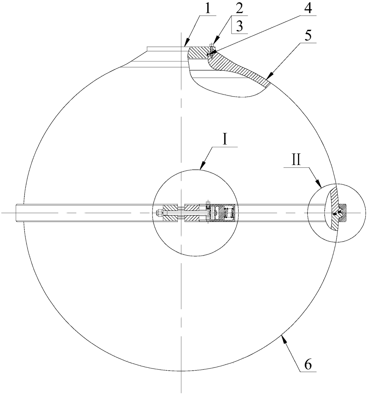
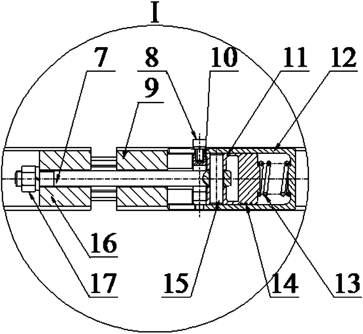
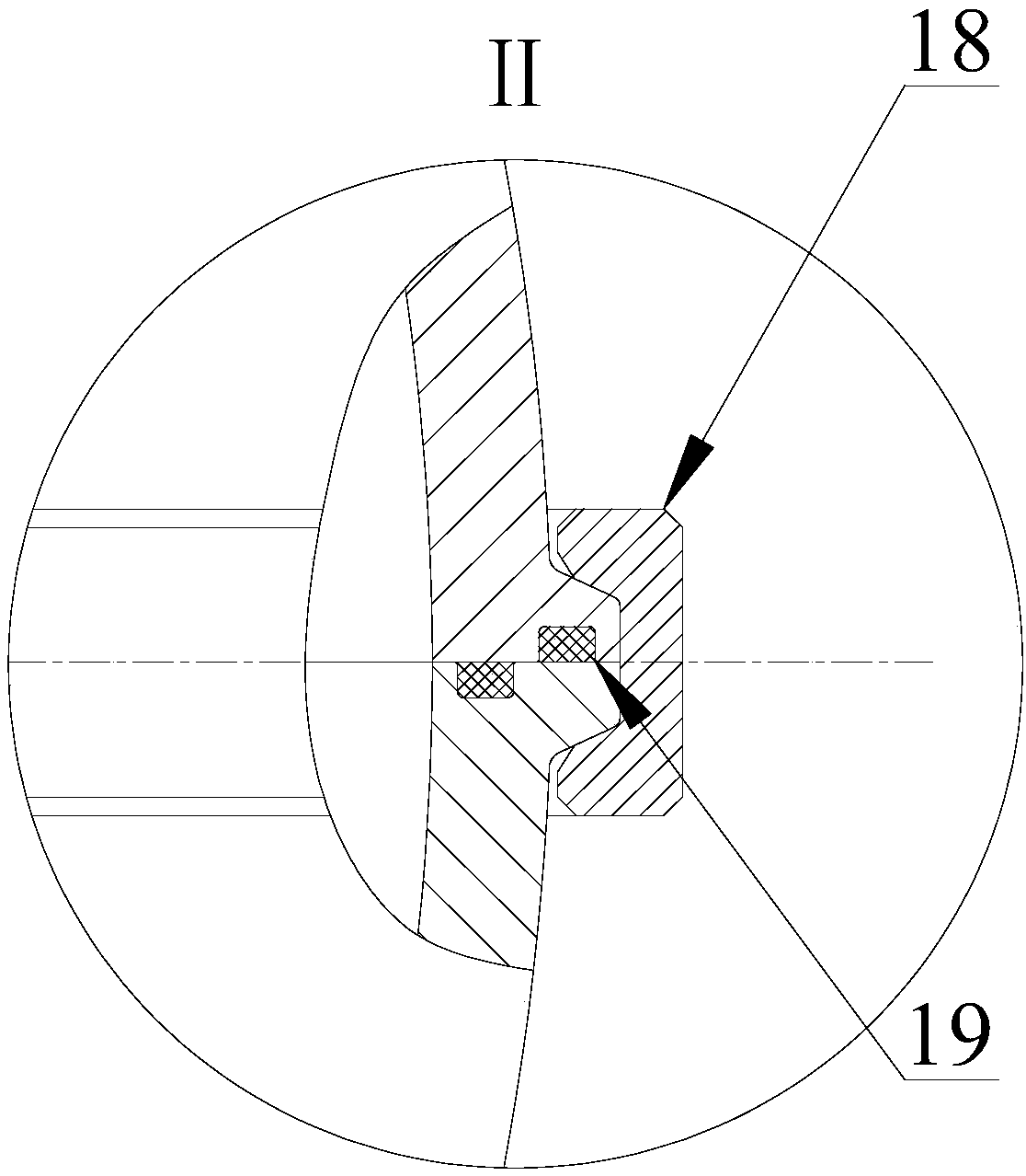
[0035] like Figure 1-6 As shown, a separate automatic locking device for submersible pressure shell clamp 18 includes a mounting block 16 arranged at one end of the clamp 18, and an installation through hole is provided in the mounting block 16 along the length direction of the clamp 18; The other end of the hoop 18 is provided with a threaded boss 9, and the center of the threaded boss 9 is provided with a through hole along the length direction of the hoop 18. The piston cylinder 12 with one end closed and one end open is provided with a connecting thread on the inner wall of the open end, and the piston cylinder 12 is passed through. The thread is connected with the threaded boss 9 on the clamp 18 . Piston cylinder 12 is provided with piston 11, is provided with three sealing rings 14 between piston 11 outer periphery and piston cylinder ...


PUM


Abstract

The invention discloses an automatic split submarine pressure shell hoop locking device which is good in locking effect and enhances safety of a pressure shell. The locking device comprises a mounting block mounted at one end of a hoop, at least one mounting through hole is formed in the mounting block along the length direction of the hoop, a piston cylinder is arranged at the other end of the hoop, one end of the piston cylinder is closed, the other end of the piston cylinder is opened, an opening side of the piston cylinder faces a notch of hoop, a piston is arranged in the piston cylinder, a sealing ring is arranged between the periphery of the piston and the inner wall of the piston cylinder, a limit block for limiting position of the piston is arranged on one side close to the opening end in the piston cylinder, a positioning pin seat is arranged on one side close to an opening of the piston cylinder on the piston, a positioning pin is arranged in the positioning pin seat, at least one locking rod matched with the mounting through holes rotatably sleeves the positioning pin, the ends of the locking rods penetrate the mounting block, and locking nuts are arranged on the ends of the locking rods through threads. The invention further discloses a split submarine pressure shell with the locking device.

Description

technical field [0001] The invention relates to an automatic locking device for a detached submersible pressure shell clamp and a detached submersible pressure shell using the locking device. Background technique [0002] As an important part of the submersible, the pressure hull plays a role in ensuring the normal operation of the internal equipment during the dive and the health and safety of personnel when manned. Its weight accounts for 1 / 4-1 / 2 of the total weight of the submersible. The design of the pressure hull has an important impact on the performance of the submersible such as safety, maneuverability, space utilization and man-machine environment. [0003] There are two main types of pressure hull structures for active submersibles: [0004] (1) One is a welded pressure shell. The differences in the manufacturing process of titanium alloy spherical shells in various countries are mainly in the hemispherical forming and welding process. One is a titanium alloy s...

Claims


Application Information

Patent Timeline
Patent Type & Authority Patents(China)
IPC IPC(8): B63C11/02B63C11/00
CPCB63C11/00B63C11/02B63C2011/027
Inventor 张建王月阳王芳张猛崔维成唐文献杨青松胡勇
Owner SHANGHAI OCEAN UNIV
Why Eureka
Try Eureka