Rotary cutting insert and tool having declined axial support surfaces

A cutting insert, supporting surface technology, used in cutting inserts, manufacturing tools, drill accessories, etc., can solve problems such as stress concentration, cracked shank, fatigue, etc.

Active Publication Date: 2020-02-14
SANDVIK INTELLECTUAL PROPERTY AB
View PDF12 Cites 0 Cited by
  • Summary
  • Abstract
  • Description
  • Claims
  • Application Information

AI Technical Summary

Problems solved by technology

[0005] However, existing drilling tool assemblies are disadvantageous in many ways
First, it is often difficult to install and remove blades within the above types of rotating assemblies
Furthermore, the loading forces of the above arrangements encountered during use will generally induce stress and fatigue at the mounting area of ​​the shank, leading to stress concentrations, cracks and shank failure

Method used


Image

  • Rotary cutting insert and tool having declined axial support surfaces
  • Rotary cutting insert and tool having declined axial support surfaces
  • Rotary cutting insert and tool having declined axial support surfaces

Examples


Embodiment Construction

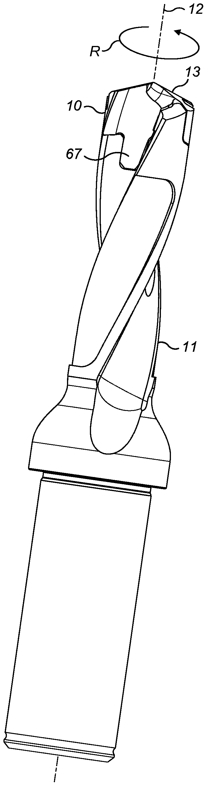
[0036] refer to figure 1 , the cutting tool embodied as a drilling tool comprises an elongated support body 11 . The cutting insert 10 is releasably mounted at the axial front end of the support body 11 . The insert 10 includes an axially forwardmost axially forward-facing cutting region 13 and an axially rearmost mounting region 67 . The mounting area 67 and the axial front end of the support body 11 are shaped to complement each other axially and radially as described in detail below in order to provide control over the transfer of load forces between the blade 10 and the support body 11 during use and management. Such load forces include axial and radial forces in addition to the torque generated by the cutting tool rotating in direction R about a central longitudinal axis 12 extending through the insert 10 and support body 11 .

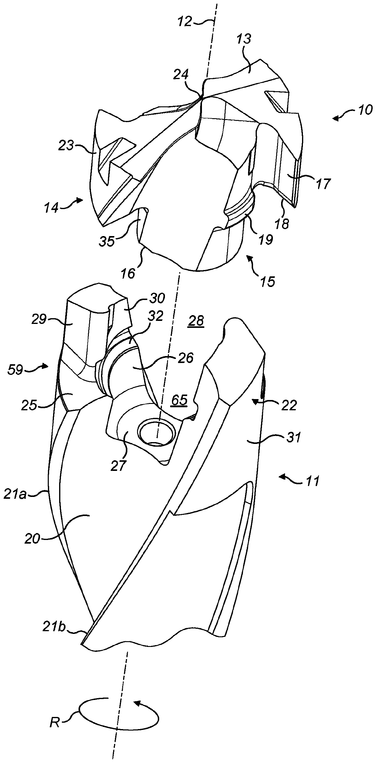
[0037] refer to figure 2 , the blade 10 may be considered to include an axially forward head 14 radially enlarged relative to a generally cy...


PUM


Abstract

A cutting insert for a rotary drill tool and drill tool assembly in which an insert and a support body are coupled via a plurality of axial support surfaces. The support surfaces comprise a first declined orientation in the axial direction and a second declined orientation in the circumferential direction so as to manage and control transmission of loading forces at the region of mounting the insert at the support body.

Description

technical field [0001] The present invention relates to a rotary drilling tool insert and a drilling tool assembly in which the insert can be mounted to a support to maximize insert retention while minimizing stress and fatigue at the support. Background technique [0002] Multi-part drilling tool assemblies have been developed in which inserts formed of hard expensive materials such as cemented carbide, ceramics, etc. are locked axially and radially in a releasable manner At knives or carriers formed from less hard, less expensive materials. Inserts are generally considered wear parts and are provided with an axially forward-facing cutting zone, which typically includes a series of cutting edges and cutting surfaces. [0003] The transfer of axial load forces and torque from the insert to the drill body needs to be controlled and managed to securely mount the insert during use while enabling the insert to be replaced once worn. Bayonet-type locking interfaces have been de...

Claims


Application Information

Patent Timeline
Patent Type & Authority Applications(China)
IPC IPC(8): B23B51/02
CPCB23B2251/02B23B51/02B23B2200/28B23B2240/32B23B2251/04B23B51/0005
Inventor 海伦娜·帕贝尔
Owner SANDVIK INTELLECTUAL PROPERTY AB
Why Eureka
Try Eureka