Tensile force exercise equipment and exercise method
A kind of exercise equipment and tension technology, applied in gymnastic equipment, muscle training equipment, sports accessories, etc., can solve the problems of shortening the exerciser's planned exercise time and affecting the effect of exercise
- Summary
- Abstract
- Description
- Claims
- Application Information
AI Technical Summary
Problems solved by technology
Method used
Image
Examples
Embodiment 1
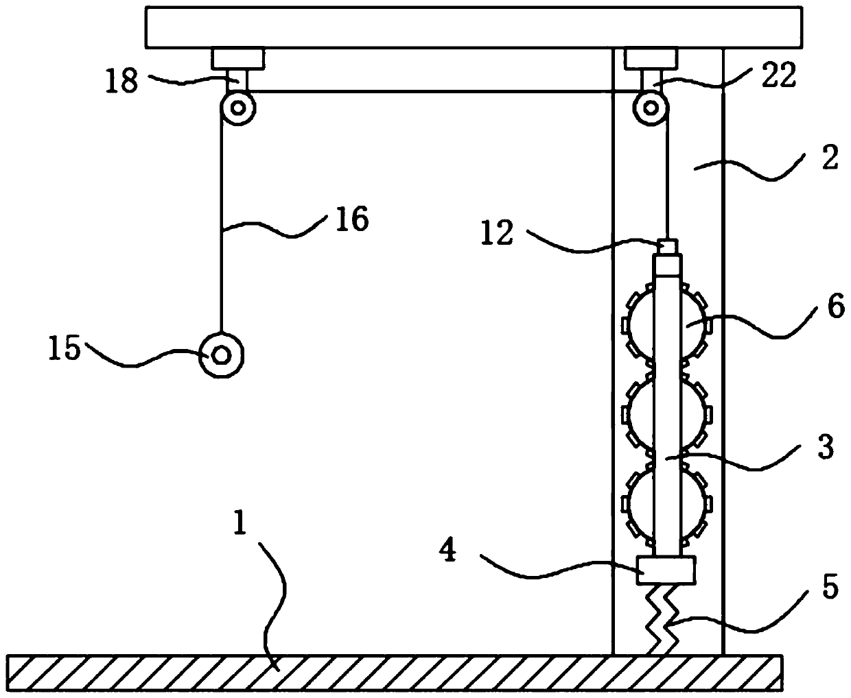
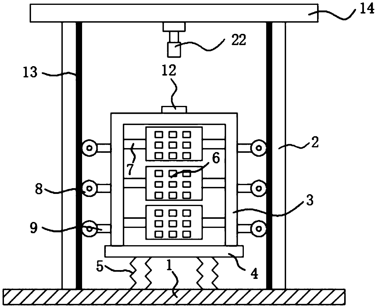
[0024] Such as Figure 1-2 As shown, a kind of tension exercise equipment comprises a base 1, two vertically arranged support rods 2 are fixedly installed on the base 1, a connecting rod 4 is arranged between the two supporting rods 2, and the connecting rod 4 is stretched through a plurality of The spring 5 is fixedly connected to the base 1. By pulling the tension ring 15 up and down, the inverted U-shaped plate 3 can be driven to move up and down. During the up-and-down movement of the inverted U-shaped plate 3, the tension spring 5 is deformed. When the tension spring 5 When the amount of deformation that occurs is large, the strength required by the exerciser is also large. The purpose of exercising the exerciser is achieved through the deformation and recovery of the stretch spring 5. Traditionally, the weight of the stretch is changed by changing the counterweight. People need to replace the counterweights of different weights many times, and the use has certain limitat...
Embodiment 2
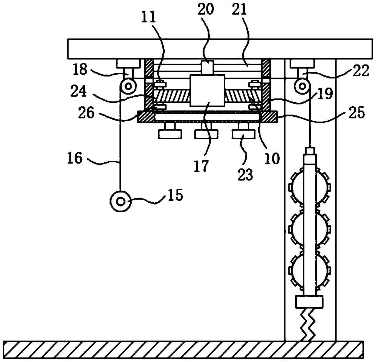
[0030] In this example, if image 3, a ventilation mechanism is provided between the first fixed pulley 18 and the second fixed pulley 22, the ventilation mechanism includes a push block 17 fixedly connected on the steel cable 16, between the push block 17 and the first fixed pulley 18 and the second fixed pulley 22 Both are vertically provided with connecting rods 19, the upper end of the connecting rods 19 is fixedly connected with the support force plate 14, the push block 17 is connected with the two connecting rods 19 through a limit mechanism, and the connecting rods 19 are provided with holes for the steel cables 16 to pass through. The movable port, the limit mechanism includes a slide bar 21 fixedly installed between the two connecting rods 19, the slide bar 21 is slidably connected with the push block 17 through the slide block 20, the limit mechanism can guide the push block 17, cooperate with the slide block 20 and the interaction between the slide bar 21 makes the...
PUM
 Abstract
Description
Claims
Application Information
 - R&D
- Intellectual Property
- Life Sciences
- Materials
- Tech Scout
- Unparalleled Data Quality
- Higher Quality Content
- 60% Fewer Hallucinations
Browse by: Latest US Patents, China's latest patents, Technical Efficacy Thesaurus, Application Domain, Technology Topic, Popular Technical Reports.
© 2025 PatSnap. All rights reserved.Legal|Privacy policy|Modern Slavery Act Transparency Statement|Sitemap|About US| Contact US: help@patsnap.com


