Rehabilitation wheelchair for promoting joint function recovery of patient with amyotrophy

A technology for joint function and muscle atrophy, which is applied in vehicle ambulance, passive exercise equipment, massage auxiliary products, etc. It can solve problems such as training and inability to help legs move joints, so as to cultivate positive emotions and promote joint pain. Functional recovery, beneficial effect on rehabilitation

Inactive Publication Date: 2022-04-05
胡宇超
View PDF1 Cites 2 Cited by
  • Summary
  • Abstract
  • Description
  • Claims
  • Application Information

AI Technical Summary

Problems solved by technology

[0008] In order to overcome the disadvantages that there are few wheelchairs suitable for muscular atrophy patients in the prior art, and they cannot help people to carry out leg joint training, the technical problem is to provide a wheelchair that can help muscular atrophy patients to perform leg joint activities, and can make The patient performs massage exercises independently, which is beneficial to the rehabilitation of the patient. A rehabilitation wheelchair for patients with muscle atrophy to promote the recovery of joint function.

Method used


Image

  • Rehabilitation wheelchair for promoting joint function recovery of patient with amyotrophy
  • Rehabilitation wheelchair for promoting joint function recovery of patient with amyotrophy
  • Rehabilitation wheelchair for promoting joint function recovery of patient with amyotrophy

Examples


Embodiment 1

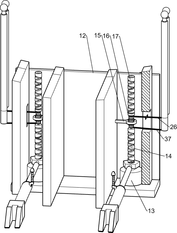
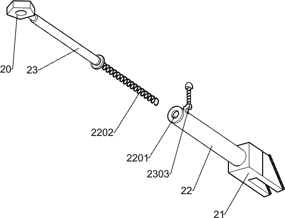
[0037] A rehabilitation wheelchair for patients with muscular atrophy to promote the recovery of joint function, such as figure 2 , image 3 , Figure 4 Figure 5 , Figure 7 , Figure 9 , Figure 10 with Figure 13 Shown, include vehicle frame 1, rear wheel 2, front wheel 3, rear frame 4, handrail 5, base 6, first rotating shaft 7, lift plate 8, lift leg shaft 10, lift plate 11, foot Pedal 1101, function box 12, lower bearing seat 13, lower screw mandrel 14, motor support 15, two-way motor 16, lower control mechanism, upper control mechanism, upper screw mandrel 17, upper bearing seat 1701, upper screw nut 18, upper Lifting rod 19, upper sliding rod 1901, upper connecting rod 1902, upper spring 1903, lower screw nut 20 and telescopic mechanism, two rear wheels 2 are connected symmetrically on the rear side of the vehicle frame 1, and the symmetrical rotation on the front side of the vehicle frame 1 Two front wheels 3 are connected, and the wheelchair can be moved by t...

Embodiment 2

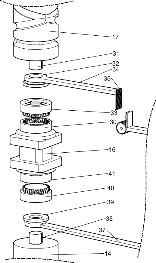
[0040] On the basis of Example 1, such as Figure 5 , Image 6 , Figure 7 with Figure 12As shown, the lower control mechanism includes a control box 24, a second control sleeve 36, a second limit spring 3602, a second limit ring 3603, a second control rod 3604, a second control bar 37, a second connecting shaft 38, The second control shaft 39, the second connecting disc 40 and the second power disc 41, the handrails 5 on the left and right sides are all affixed with a control box 24, and the control box 24 is affixed with a second control sleeve 36. There are two second annular grooves 3601 in the two control sleeves 36, and four second limit springs 3602 are connected in an annular array in the second annular grooves 3601, and the second limit springs 3602 in each second annular groove 3601 A second limiting ring 3603 is fixedly connected to the spring 3602. The second limiting ring 3603 is an elastic ring that can become larger under the force of expansion. When the sec...

Embodiment 3

[0043] On the basis of Example 2, such as Figure 5 , Image 6 , Figure 7 , Figure 8 , Figure 11 with Figure 12 As shown, the upper control mechanism includes a first control sleeve 25, a first limit spring 2502, a first limit ring 2503, a first control rod 2504, a first control bar 26, a first rack 27, and a control rod 28 , the control gear 29, the first power disc 30, the first connecting shaft 31, the first control shaft 32, the first connecting disc 33, the first control block 34 and the second rack 35, the control box 24 is all fixedly connected with the first A control sleeve 25, the first control sleeve 25 is provided with two first annular grooves 2501, and the first annular groove 2501 is connected with four first limit springs 2502 in an annular array, and each first annular groove 2501 A first limiting ring 2503 is jointly fixed on the first limiting spring 2502 inside, the first limiting ring 2503 is an elastic ring, which can become larger under the forc...


PUM


Abstract

The invention relates to a rehabilitation wheelchair, in particular to a rehabilitation wheelchair for promoting joint function recovery of a patient with amyotrophy. The rehabilitation wheelchair for promoting joint function recovery of the patient with the amyotrophy can help the patient with the amyotrophy to conduct leg joint movement and enable the patient to conduct massage movement independently, and rehabilitation of the patient is facilitated. The invention discloses a rehabilitation wheelchair for promoting joint function recovery of a patient with amyotrophy. The rehabilitation wheelchair comprises a frame, rear wheels, front wheels, a rear frame, a handrail frame, a base, a first rotating shaft, an upper lifting plate, a leg lifting shaft, a lower lifting plate, a pedal plate, a functional box, a lower bearing seat and the like, and two rear wheels are symmetrically and rotationally connected to the rear side of the frame. The leg joint movement training device can help a patient to carry out leg joint movement training, and the thighs or the shanks can be exercised independently.

Description

technical field [0001] The invention relates to a rehabilitation wheelchair, in particular to a rehabilitation wheelchair for patients with muscular atrophy to promote joint function recovery. Background technique [0002] Muscle atrophy refers to the reduction in muscle volume caused by rhabdomyotrophy, muscle fiber thinning or even disappearance, etc., mostly caused by muscle diseases or nervous system dysfunction. Patients with muscular atrophy are bedridden for a long time due to muscle atrophy and muscle weakness, and are prone to pneumonia , pressure sores, etc., and most patients have symptoms of bulbar paralysis, which poses a great threat to the lives of patients. [0003] Among the currently existing related types of technical solutions, Chinese patent 202020835383.1 discloses a lifting wheel suitable for people with loss of lower limbs and muscle atrophy, including a chair and a lifting mechanism. The lower side of the chair is connected to the lifting mechanism, ...

Claims


Application Information

Patent Timeline
Patent Type & Authority Applications(China)
IPC IPC(8): A61G5/04A61G5/10A61H15/00A61H1/02
Inventor 胡宇超
Owner 胡宇超
Why Eureka
Try Eureka