Retractable supporting structure and hospital bed lifting mechanism

A support structure and telescopic technology, applied in the direction of hospital beds, lifting frames, lifting devices, etc., can solve the problems of inconvenience for patients to get on and off the bed, reduce the patient's treatment experience, and the screw-driven support structure occupies a large space. The effect of large reach and volume reduction

Active Publication Date: 2014-12-03
SHANGHAI UNITED IMAGING HEALTHCARE
View PDF9 Cites 11 Cited by
  • Summary
  • Abstract
  • Description
  • Claims
  • Application Information

AI Technical Summary

Problems solved by technology

However, refer to figure 2 As shown, in the actual use process, after the telescopic support 4 shrinks, if the lead screw 1 is too long, the upper end of the lead screw 1 will be against the bed board 6, so that the telescopic support 4 cannot be further con

Method used


Image

  • Retractable supporting structure and hospital bed lifting mechanism
  • Retractable supporting structure and hospital bed lifting mechanism
  • Retractable supporting structure and hospital bed lifting mechanism

Examples


Embodiment 1

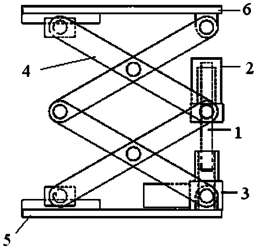
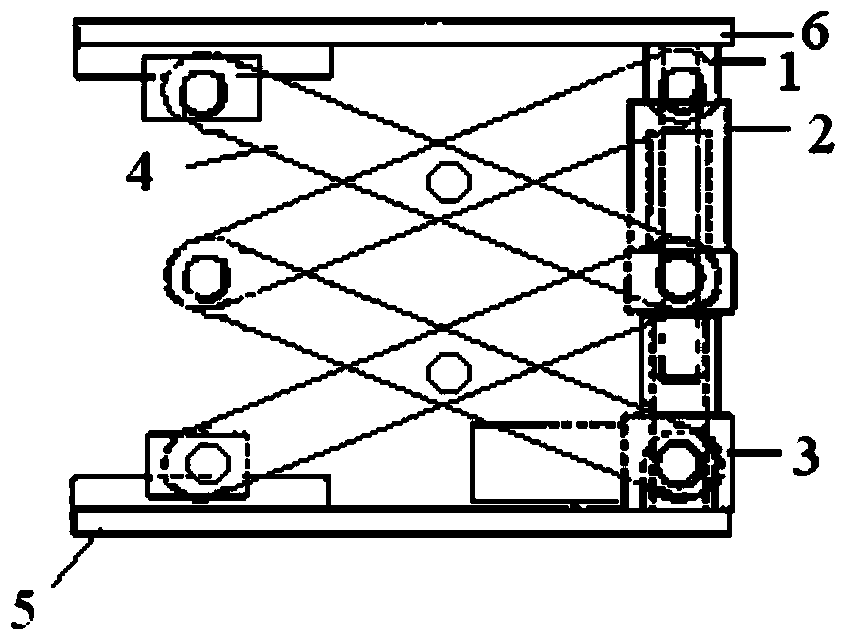
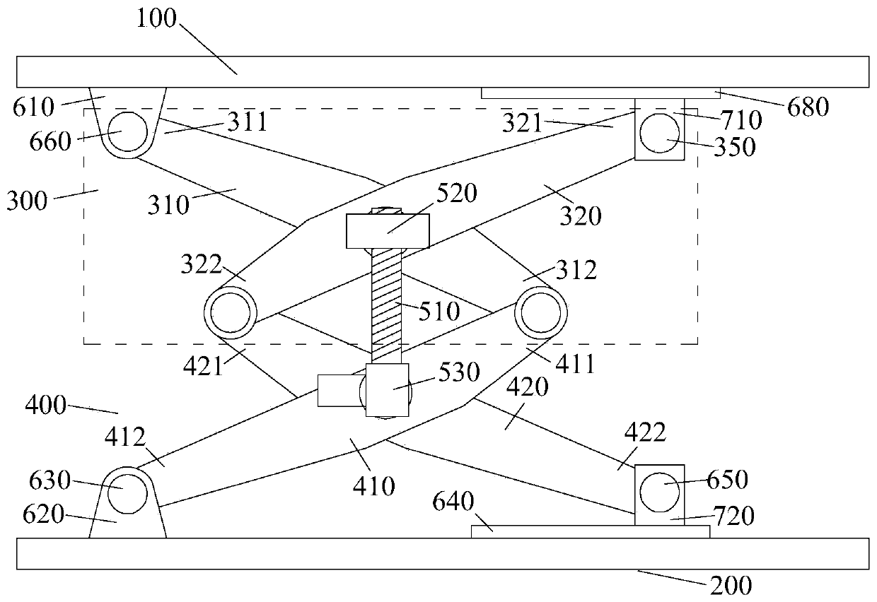
[0052] Figure 3 ~ Figure 6 It is a structural schematic diagram of the telescopic support structure provided by this embodiment. in, image 3 It is a schematic diagram of the front structure after the expansion of the telescopic support structure; Figure 4 It is a schematic diagram of the back structure after the telescopic support structure is deployed; Figure 5 It is a schematic diagram of the rear structure of the telescopic support structure after contraction; Image 6 It is a schematic diagram of the front structure of the retractable support structure.

[0053] combined reference image 3 with Figure 4 As shown, the telescopic support structure provided by this embodiment includes: a telescopic bracket and a screw drive mechanism. The telescopic bracket is composed of multiple groups of scissor brackets, and the multiple groups of scissor brackets are arranged along the first direction. Wherein, one group of scissors brackets includes two poles, the two poles ...

Embodiment 2

[0082] The technical solution provided by this embodiment and embodiment 1 is roughly the same, refer to Figure 10 As shown, the telescopic support structure provided by this embodiment includes a scissors support 300 and a scissors support 900 .

[0083] Compared with the telescopic support structure in Embodiment 1, the difference lies in that the scissors support 900 includes two struts 910 and 920 that are articulated crosswise. The lower end 912 of the pole 910 is movably connected with the base 620, and the upper end 911 is movably connected with the lower end 312 of the pole 310 of the scissors support 300; the lower end 922 of the pole 920 is movably connected with the slider 720, and the upper end 921 It is flexibly connected with the lower end 322 of the pole 320 of the scissors support 300 . Moreover, the cross connection point of the struts 910 and 920 is located in the middle of the struts 910 and 920 .

[0084] The structure of the scissors support 300 is simi...


PUM


Abstract

The invention provides a retractable supporting structure and a hospital bed lifting mechanism. The retractable supporting structure comprises a plurality of groups of scissor supports which are arranged along a first direction, and a lead screw driving mechanism which is used for controlling the groups of scissor supports to retract in the first direction, wherein the groups of scissor supports comprise at least one group of scissor supports; on supporting rods of the group of scissor supports, the distance from a connection point between two supporting rods to one end of each supporting rod is greater than the distance from the connection point to the other end of each supporting rod; a nut or a motor of the lead screw driving mechanism is located on the group of scissor supports; the ends, closer to the connection point between the two supporting rods of the group of scissor supports, of the supporting rods of at least one group of scissor supports are located on both sides of a connecting wire of the nut and the motor respectively. Compared with an existing retractable supporting structure, the retractable supporting structure has the advantages that the nut on a lead screw is capable of increasing the retracting stroke of the scissor supports under the condition that the moving distances are the same.

Description

technical field [0001] The invention relates to the mechanical field, in particular to a telescopic support structure and a hospital bed lifting mechanism. Background technique [0002] A telescoping support structure is a common mechanical transmission. During the expansion and expansion process, the telescopic support structure can provide a strong support force, and the variable motion stroke can meet the needs of different usage scenarios. Therefore, the telescopic support structure is widely used in the field of mechanical transmission. [0003] For example, in the field of medical equipment, including CT machines (computed tomography scans), PET-CT machines (positron emission computed tomography scans), etc., retractable hospital beds are required to support patients, so that patients can be adjusted vertically. inspection angle. Moreover, in the field of medical equipment, there is not only a large movement stroke requirement for the telescopic support structure, b...

Claims


Application Information

Patent Timeline
IPC IPC(8): B66F7/06B66F7/28A61B6/04A61G7/00
Inventor 王益宁包光中张剑任鸿涛代习伟
Owner SHANGHAI UNITED IMAGING HEALTHCARE
Why Eureka
Try Eureka