
Mixed stirring material conveying mechanism

A conveying mechanism, mixing and stirring technology, applied in the direction of the supply device, forming pressure head, manufacturing tools, etc., can solve the problems affecting the movement accuracy, etc., to achieve the effect of ensuring the compaction effect, simple manufacturing, and low movement accuracy requirements

Inactive Publication Date: 2020-02-18
吴明海
View PDF6 Cites 0 Cited by
  • Summary
  • Abstract
  • Description
  • Claims
  • Application Information

AI Technical Summary

Problems solved by technology

[0002] When the existing cement bricks are being processed, the mixed material is first poured into the forming material receiving tank, and then the pressing plate is pressed into the material receiving tank through the pressing mechanism to compact and form the mixed material. The material receiving tank is generally poured into the receiving tank directly through the conveying pipe, and then moved to the bottom of the pressing mechanism through the receiving tank for compaction. It is necessary to ensure that the inner cavity of the receiving tank is The body is aligned up and down with the pressing plate of the pressing mechanism, and during operation, because the material in the mixture will block the moving mechanism of the receiving tank, affecting the moving accuracy, it is not ideal

Method used


Image

  • Mixed stirring material conveying mechanism
  • Mixed stirring material conveying mechanism

Examples


Embodiment

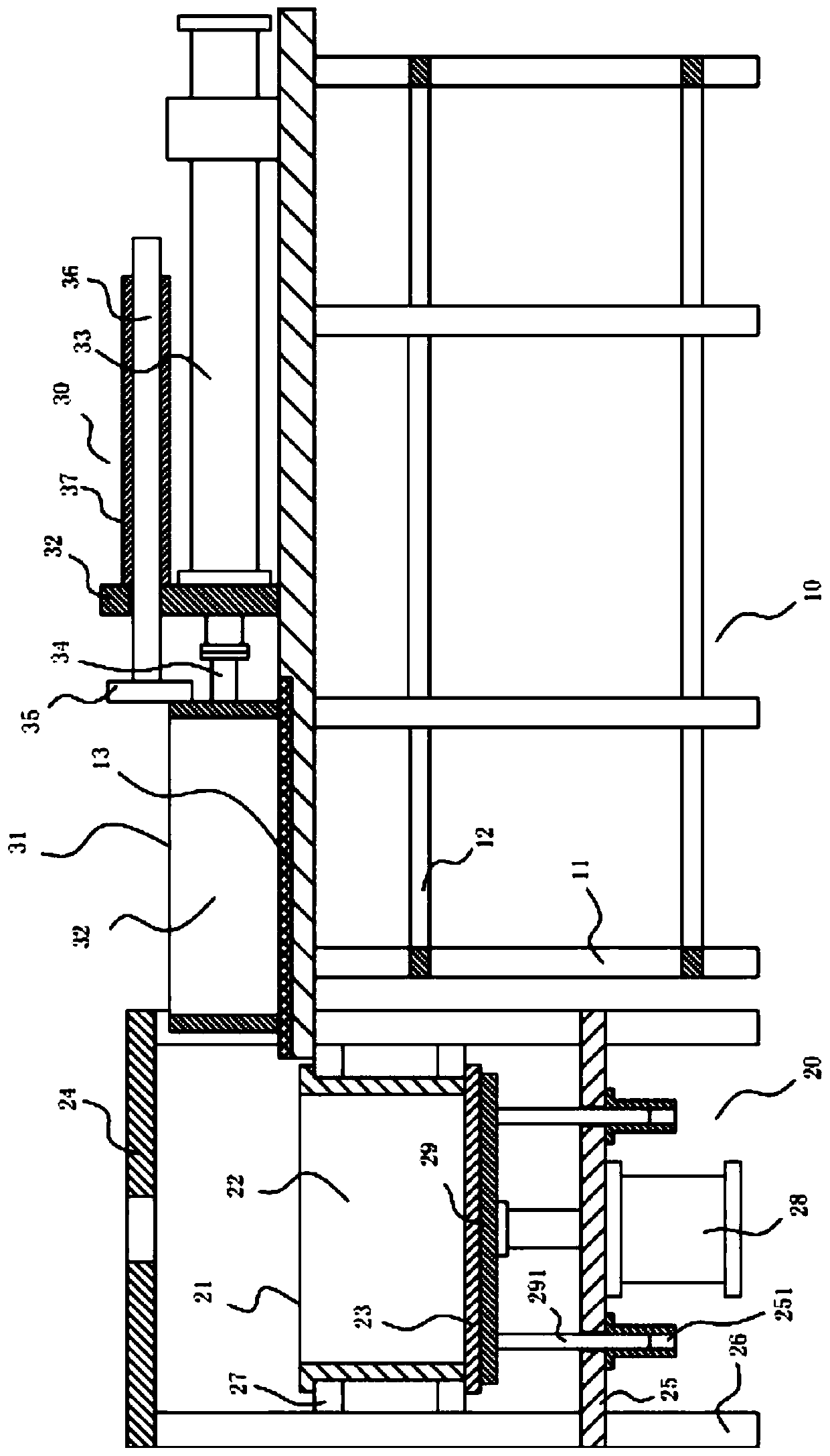
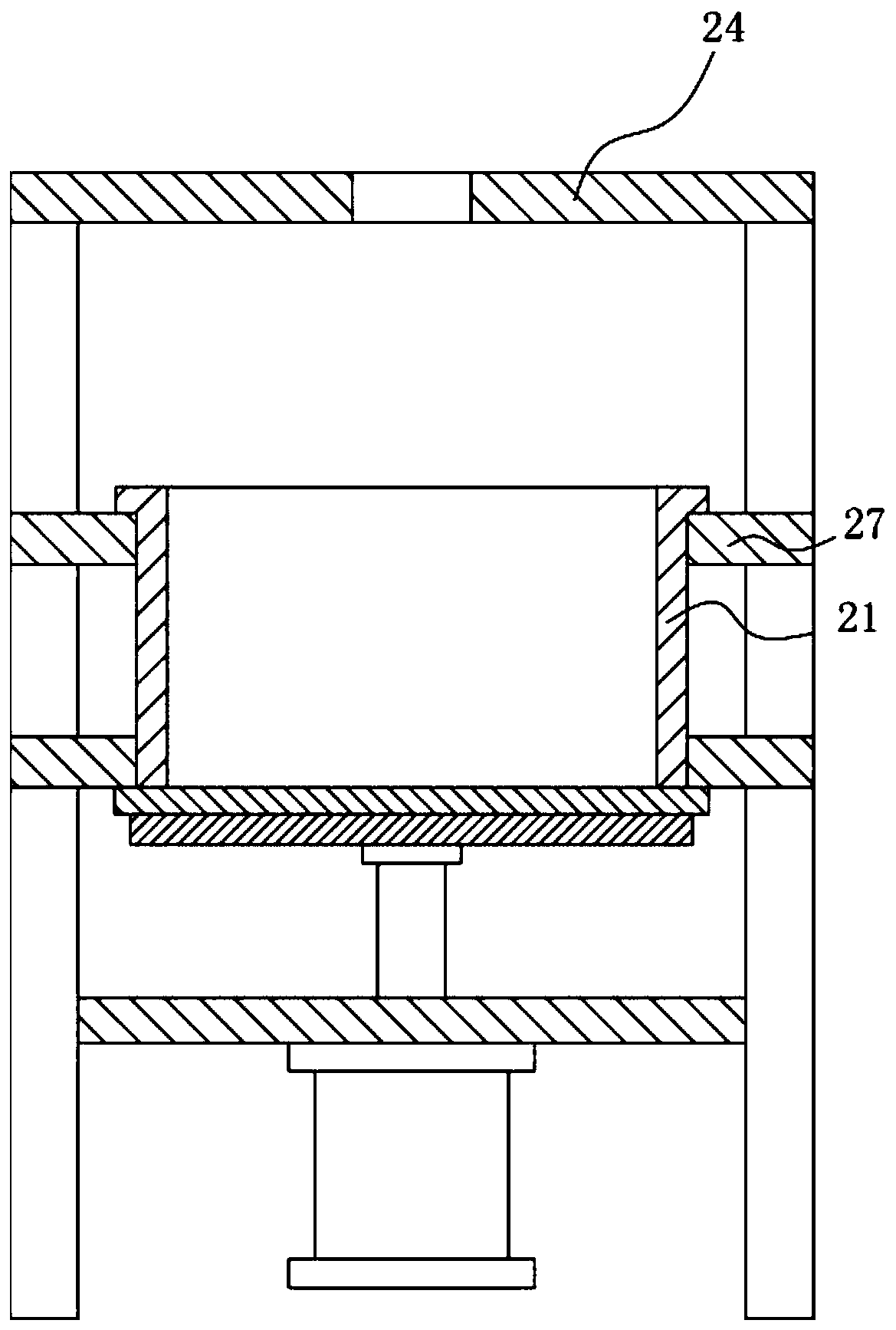
[0018] Example: see Figure 1 to Figure 2 As shown, a mixing and stirring material conveying mechanism includes a conveying frame 10 and a material receiving frame 20, and the conveying frame 10 is at the right side of the material receiving frame 20;

[0019] The top surface of the main top plate of the conveying mechanism 10 is fixed with a conveying and pushing mechanism 30, the transition housing 31 of the conveying and pushing mechanism 30 is on the top surface of the main top plate, and the interior of the transition housing 31 is provided with an inner transition cavity 32 , the middle part of the material receiving frame 20 is fixed with a material receiving housing 21, the inside of the material receiving housing 21 is formed with a material receiving cavity 22, and the bottom surface of the material receiving housing 21 is pressed against the top surface of the material receiving plate 23, The transition shell 31 corresponds to the receiving shell 21 .

[0020] Furt...


PUM


Abstract

The invention discloses a mixed stirring material conveying mechanism. The conveying mechanism comprises a conveyor rack and a material receiving rack, wherein the conveyor rack is located at the right side of the material receiving rack; a conveying pushing mechanism is fixed on the top surface of a main top plate of the conveying mechanism, a transition shell of the conveying pushing mechanism is located on the top surface of the main top plate, and an inner transition cavity is formed in the transition shell; and a material receiving shell is fixed in the middle of the material receiving frame, a material receiving cavity is formed in the material receiving shell, the bottom surface of the material receiving shell presses against the top surface of a material receiving plate, and the transition shell corresponds to the material receiving shell. According to the conveying mechanism, the mixed stirring material can be poured into the material receiving shell through the moving type transition shell, and the material receiving shell does not need to be moved, correspondence of the material receiving shell and the pressing plate of a pressing mechanism is guaranteed, and the pressing effect is guaranteed; and the moving precision requirement of the transition shell is low so as to make manufacturing of the conveying mechanism simple, and the moving feeding effect of the transition shell is influenced.

Description

technical field [0001] The invention relates to the technical field of brick making equipment, and more specifically relates to a mixing material conveying mechanism. Background technique [0002] When the existing cement bricks are being processed, the mixed material is first poured into the forming material receiving tank, and then the pressing plate is pressed into the material receiving tank through the pressing mechanism to compact the mixed material into shape. The material receiving tank is generally poured into the receiving tank directly through the conveying pipe, and then moved to the bottom of the pressing mechanism through the receiving tank for compaction. It is necessary to ensure that the inner cavity of the receiving tank is The body is aligned up and down with the pressing plate of the pressing mechanism, and in operation, because the material in the mixture will block the moving mechanism of the receiving tank body, affecting the moving accuracy, it is not...

Claims


Application Information

Patent Timeline
Patent Type & Authority Applications(China)
IPC IPC(8): B28B13/02B28B3/04
CPCB28B3/04B28B13/026
Inventor 吴明海
Owner 吴明海
Learn More