Clutch structure capable of automatically regulating center distance and speed reducer

An automatic adjustment, center distance technology, applied in clutches, one-way clutches, transmissions, etc., can solve the problems of unstable clutch performance and low service life

Pending Publication Date: 2020-02-18
深圳市弘博汇科技有限公司
View PDF1 Cites 2 Cited by
  • Summary
  • Abstract
  • Description
  • Claims
  • Application Information

AI Technical Summary

Problems solved by technology

[0004] In view of this, the present invention aims at the deficiencies in the prior art, and its main purpose is to provide a clutch structure and reducer that can automatically adjust the center distance. Unstable clutch performance and low service life

Method used


Image

  • Clutch structure capable of automatically regulating center distance and speed reducer
  • Clutch structure capable of automatically regulating center distance and speed reducer
  • Clutch structure capable of automatically regulating center distance and speed reducer

Examples


Embodiment Construction

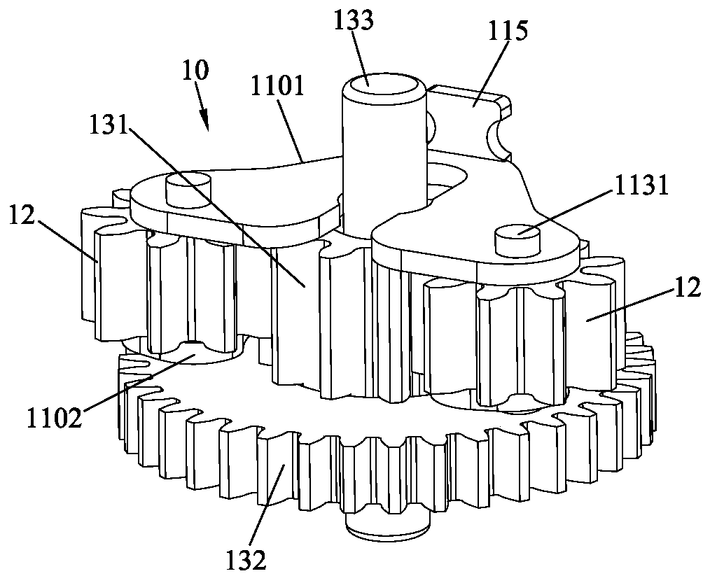
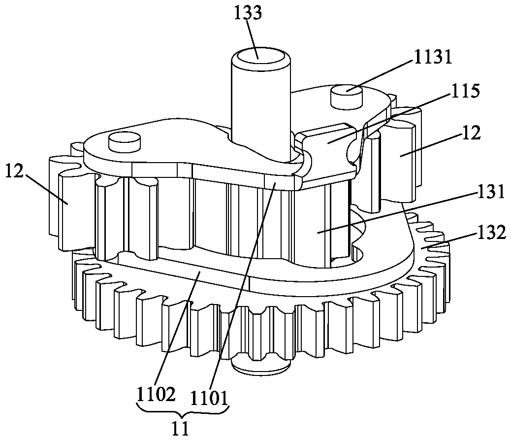
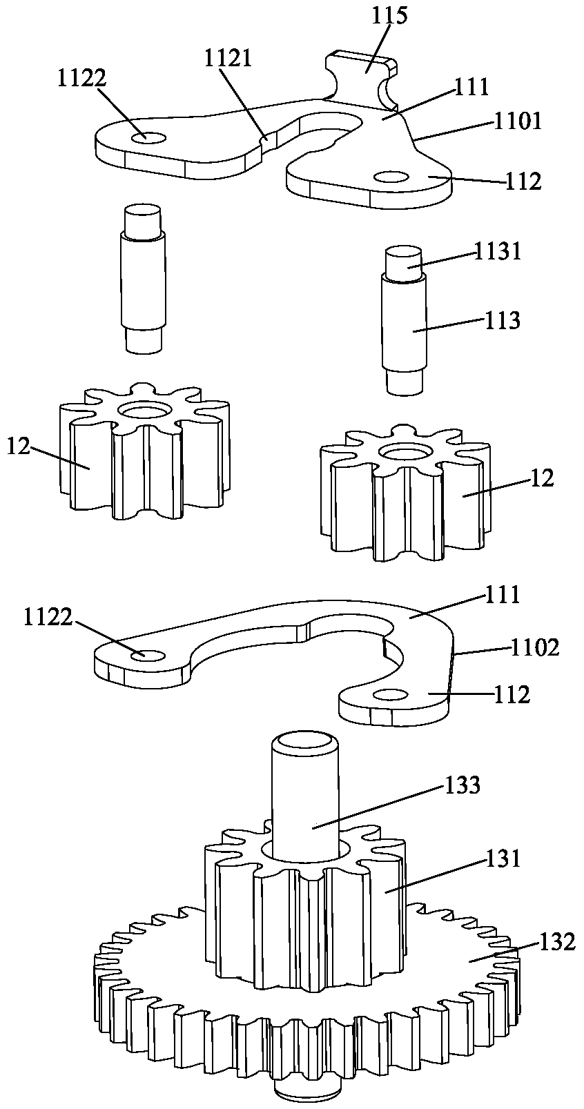
[0048] Please refer to Figure 1 to Figure 10 As shown, it shows the specific structure of the preferred embodiment of the present invention, which is a clutch structure and a speed reducer for automatically adjusting the center distance, including a clutch structure 10 and a speed reducer.

[0049] In the description of the present invention, it should be noted that the orientation or positional relationship indicated by the terms "upper", "lower", "left", "right", etc. is based on the orientation or positional relationship shown in the drawings, and is only for It is convenient to describe the present invention and simplify the description, but does not indicate or imply that the device or element referred to must have a specific orientation, be constructed and operate in a specific orientation, and thus should not be construed as limiting the present invention.

[0050] (see Figure 1 to Figure 4 As shown), the clutch structure 10 includes an elastic piece 11, a planetary ...


PUM


Abstract

The invention discloses a clutch structure capable of automatically regulating a center distance and a speed reducer. The clutch structure comprises an elastic plate, a planetary gear and a driving gear, wherein the elastic plate is arranged on the driving gear and provided with an elastic end and a clamping end; and the planetary gear is arranged at the clamping end, and the engagement of the planetary gear and the driving gear is kept by elastic force provided by the elastic plate. As the elastic plate provides elastic force, when the planetary gear and the driving gear are worn, and the center distance between the planetary gear and the driving gear can be automatically regulated by utilizing the elastic plate; a friction coefficient between the planetary gear and the driving gear cannot be reduced due to wear, the planetary gear is always engaged with the driving gear, and proper friction force is kept; and compared with the traditional swing block swinging type clutch structure, the clutch structure has the advantages that not only can the clutching stability be further improved, and the service life of the clutch structure also can be prolonged.

Description

technical field [0001] The invention relates to the technology in the field of clutch structures, in particular to a clutch structure and a speed reducer for automatically adjusting the center distance. Background technique [0002] Among the various existing clutch structures, the clutch structure using the pendulum block swing type clutch is relatively simple and more reliable to realize the clutch structure. For example, the Chinese invention patent CN 106703532 A discloses a transmission structure of an electronic lock cylinder and a clutch mode of an electronic lock using this structure. In this state, the oscillating block rotates together with the main transmission gear; the output gear is arranged on the installation housing, and when the oscillating block rotates, the driven gear can be driven to mesh with the output gear. [0003] Usually, the effect that the swinging block rotates with the driving gear is realized by the friction generated after the connection be...

Claims


Application Information

Patent Timeline
Patent Type & Authority Applications(China)
IPC IPC(8): F16H3/44F16H57/12F16H57/023F16D41/00
CPCF16H3/002F16H3/005F16H3/44F16H57/12F16H57/023F16D41/00F16H2057/127F16H2057/02034F16H37/04
Inventor 陈思祖
Owner 深圳市弘博汇科技有限公司
Why Eureka
Try Eureka