Dust collection equipment
A technology of equipment and dust, applied in the field of vacuum equipment, can solve the problems of cumbersome operation, insufficient convenience, inconvenient movement, etc.
- Summary
- Abstract
- Description
- Claims
- Application Information
AI Technical Summary
Problems solved by technology
Method used
Image

Examples
no. 1 approach
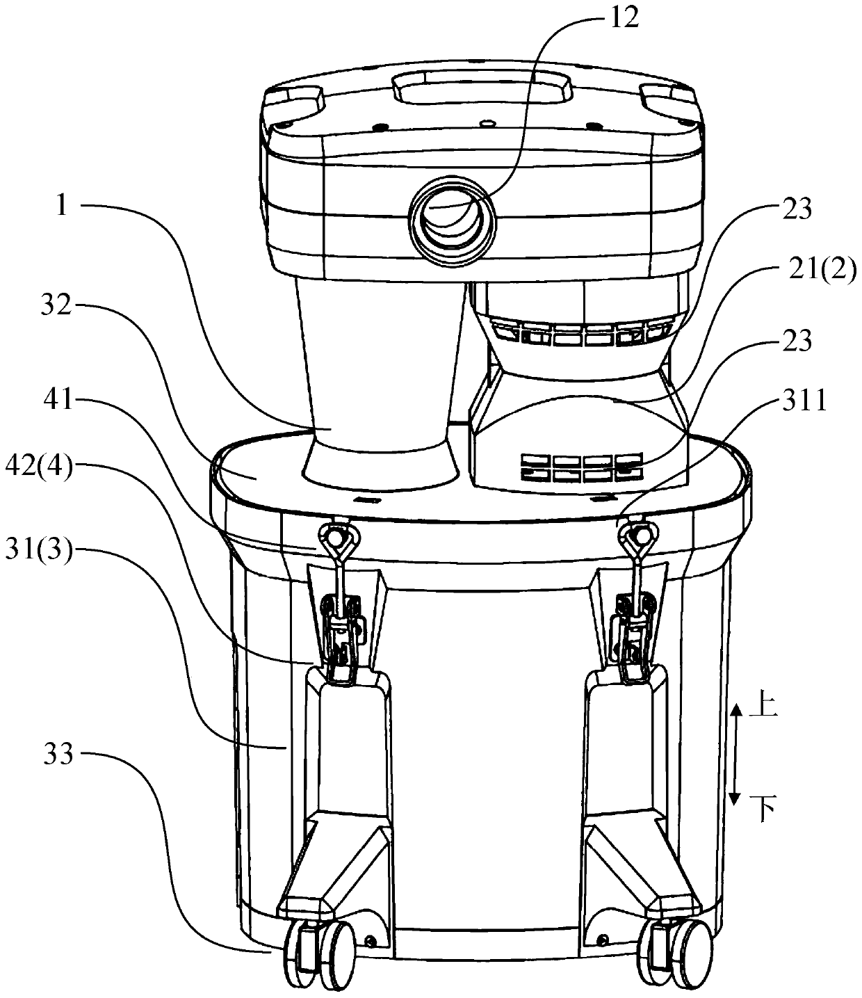
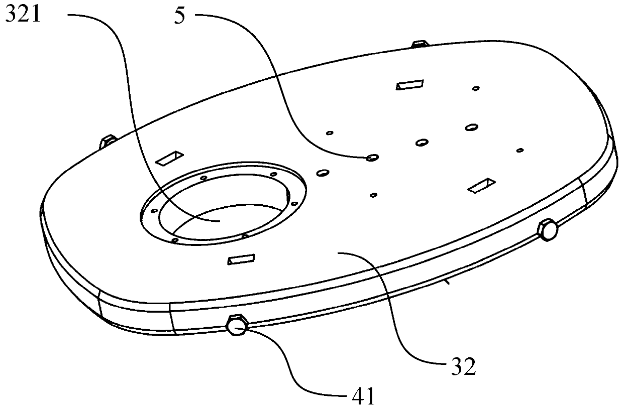
[0219] Such as Figure 1 to Figure 3 As shown, a dust collection device according to the first embodiment of the present invention includes a filter device, an airflow generating device 2 and a collection unit 3 .
[0220] It should be understood that in Figure 3 to Figure 5 and the following Figure 6 to Figure 13 , more conceptually and schematically shows the dust suction device according to various embodiments of the present invention, therefore, in Figure 3 to Figure 13 in, with figure 1 and figure 2 In comparison, some components are simplified or omitted. The dust collection equipment in this application is just a customary name, which does not mean that the dust collection equipment can only collect dust. For the sake of simplicity, the following dust also includes other solid garbage, mixed solid and liquid garbage and liquid garbage, such as food scraps, fruit residues, fruit juices, leaves, etc.
[0221] It can be understood that the filter device may be a ...
no. 2 approach
[0244] The whole structure of the dust collection device which concerns on 2nd Embodiment of this invention is the same as the whole structure of the dust collection device which concerns on 1st Embodiment of this invention. In the present embodiment, the same reference numerals are assigned to the same or similar components as those in the first embodiment, and detailed descriptions of these components will be omitted.
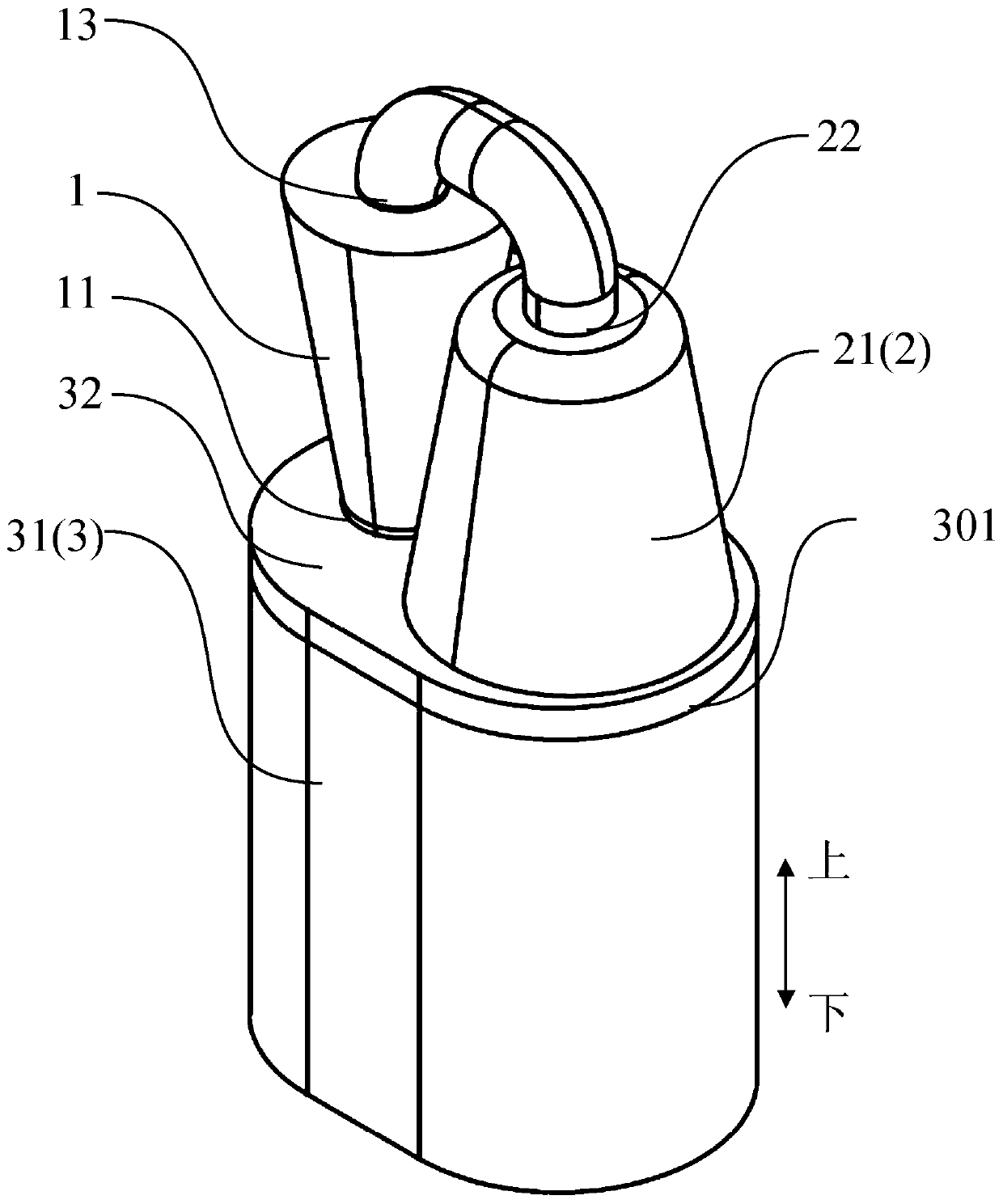
[0245] Such as Figure 6 to Figure 9 As shown, the dust collection device according to the second embodiment of the present invention includes a cyclone separation device 1 , an airflow generating device 2 and a collection unit 3 .
[0246] The airflow generating device 2 includes a motor, a fan driven by the motor, a casing 21 surrounding the motor and the fan, a secondary filter device and a secondary dust collection unit 24, and the casing 21 includes an air inlet 22 and an air outlet (not shown). The air flow generating device 2 can form a negative press...
no. 3 approach
[0260] The partial structure of the dust collection device which concerns on 3rd Embodiment of this invention is the same as the partial structure of the dust collection device which concerns on 1st Embodiment of this invention. In the present embodiment, the same reference numerals are assigned to the same or similar components as those in the first embodiment, and detailed descriptions of these components will be omitted.
[0261] Such as Figure 10 to Figure 13 As shown, the dust collection device according to the third embodiment of the present invention includes a cyclone separation device 1 , an airflow generating device 2 and a collection unit 3 . In the working mode, the mounting base 32 has a mounting surface for mounting the filtering device, the mounting surface is facing away from the cavity, and in the transport / storage mode, the mounting surface is facing the cavity.
[0262] In the first embodiment, both the airflow generating device 2 and the cyclone separatin...
PUM
 Abstract
Description
Claims
Application Information
 - R&D Engineer
- R&D Manager
- IP Professional
- Industry Leading Data Capabilities
- Powerful AI technology
- Patent DNA Extraction
Browse by: Latest US Patents, China's latest patents, Technical Efficacy Thesaurus, Application Domain, Technology Topic.
© 2024 PatSnap. All rights reserved.Legal|Privacy policy|Modern Slavery Act Transparency Statement|Sitemap