Oropharyngeal airway

An oropharyngeal ventilation tube and ventilation tube technology, which can be used in catheters, respirator and other directions, can solve the problems of tightness, discomfort and easy falling off of the patient's ear, and achieve the effect of avoiding discomfort and being easy to use.

Inactive Publication Date: 2020-02-21
杭州福疗医疗科技有限公司
View PDF0 Cites 0 Cited by
  • Summary
  • Abstract
  • Description
  • Claims
  • Application Information

AI Technical Summary

Problems solved by technology

[0003] The object of the present invention is to provide an oropharyngeal ventilation tube to solve the problem that the existing oropharyngeal ventilation tube proposed in the above-mentioned background technology is easy to fall off after t...

Method used


Image

  • Oropharyngeal airway
  • Oropharyngeal airway
  • Oropharyngeal airway

Examples


Embodiment 1

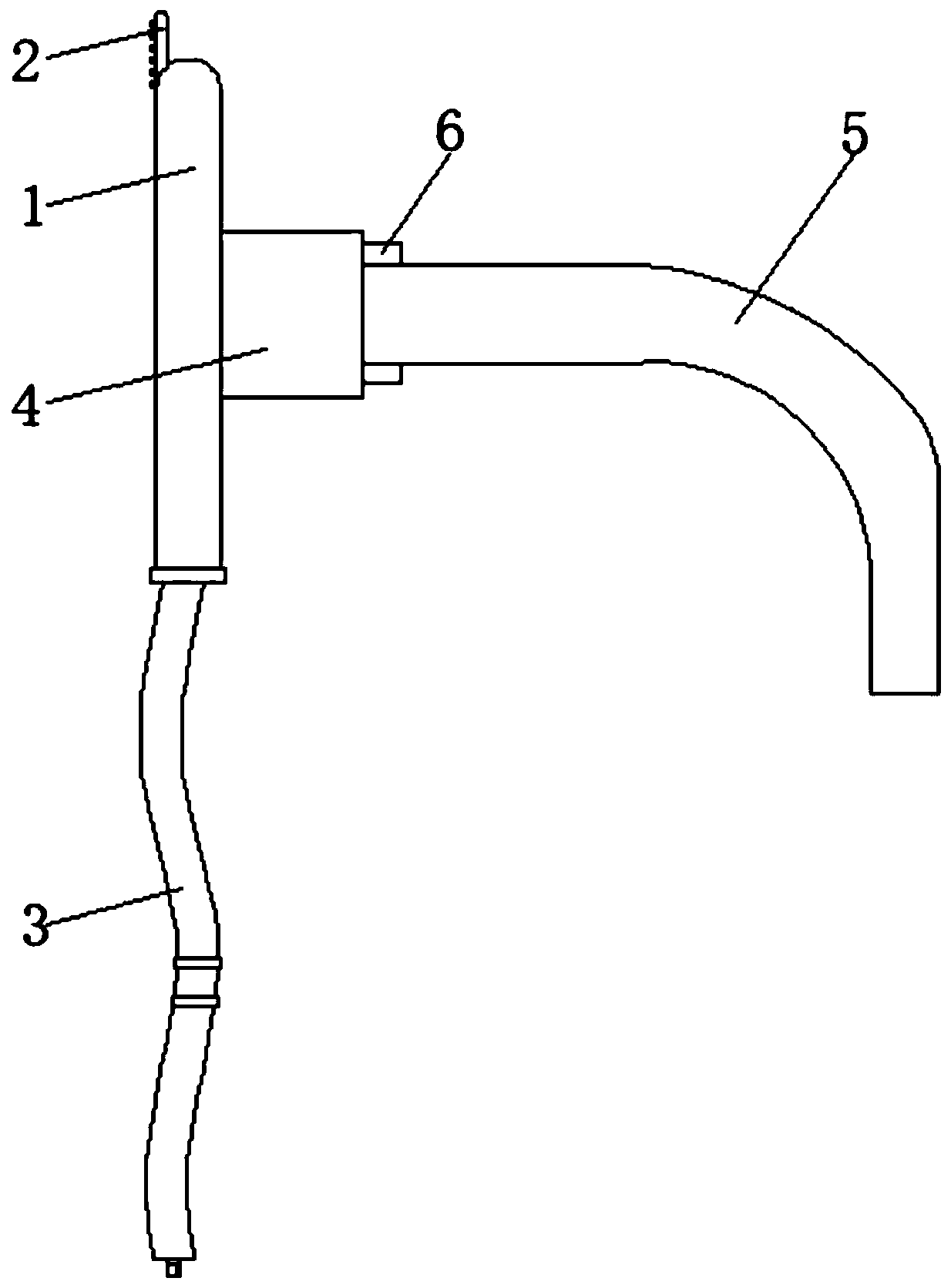
[0021] see Figure 1-3 , the present invention provides a technical solution: oropharyngeal airway, including a flange 1, the top of the flange 1 is embedded with a connecting plate mechanism 2, the bottom of the flange 1 is connected with a connecting rope 3, and one side of the flange 1 is installed There is a dental pad 4, the other side of the dental pad 4 is equipped with a vent pipe main body 5, and the side of the dental pad 4 near the vent pipe main body 5 is provided with a positioning mechanism 6.

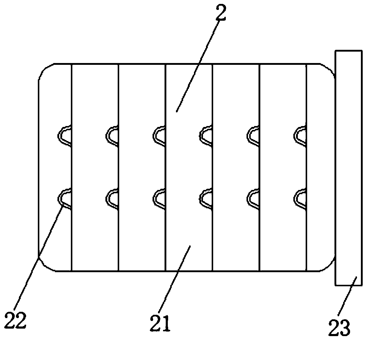
[0022] In this embodiment, preferably, the connecting plate mechanism 2 includes a mounting plate 21 , a positioning buckle 22 is disposed on the front of the mounting plate 21 , and a connecting block 23 is mounted on one side of the mounting plate 21 .

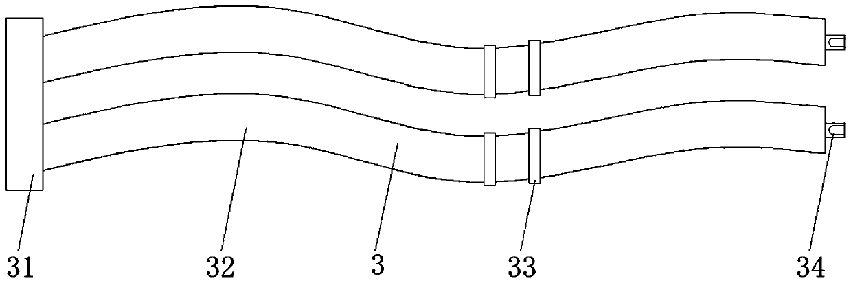
[0023] In this embodiment, preferably, the connecting rope 3 includes a mounting block 31, an elastic band 32 is installed on one side of the mounting block 31, a movable buckle 33 is movably connected to the outside of...

Embodiment 2

[0027] see Figure 1-4 , the present invention provides a technical solution: oropharyngeal airway, including a flange 1, the top of the flange 1 is embedded with a connecting plate mechanism 2, the bottom of the flange 1 is connected with a connecting rope 3, and one side of the flange 1 is installed There is a dental pad 4, the other side of the dental pad 4 is equipped with a vent pipe main body 5, and the side of the dental pad 4 near the vent pipe main body 5 is provided with a positioning mechanism 6.

[0028] In this embodiment, preferably, the connecting plate mechanism 2 includes a mounting plate 21 , a positioning buckle 22 is disposed on the front of the mounting plate 21 , and a connecting block 23 is mounted on one side of the mounting plate 21 .

[0029] In this embodiment, preferably, the connecting rope 3 includes a mounting block 31, an elastic band 32 is installed on one side of the mounting block 31, a movable buckle 33 is movably connected to the outside of...


PUM


Abstract

The invention discloses an oropharyngeal airway. The oropharyngeal airway includes a flange, a connecting plate mechanism is embeddedly installed into the top of the flange, the bottom of the flange is connected with a connecting rope, a dental pad is installed on one side of the flange, an airway main body is installed on the other side of the dental pad, and one side, close to the airway main body, of the dental pad is provided with a positioning mechanism. After the airway main body is inserted into a patient, the connecting rope can be wound from the outside of a patient head, hooks are combined with positioning buckles to complete fixing of the device, so that the device is prevented from falling off from a patient mouth, at the same time a way of connecting a lanyard from ears is abandoned, and discomfort to the patient ears is avoided; and fixing of the outer side of the airway main body can be completed by using a way of clamping from the outer side, so that the problem that the other end damages a patient throat or the patient throat is stimulated and vomited due to change in angle is avoided, and the easy-to-use effect is achieved.

Description

technical field [0001] The invention belongs to the technical field of medical devices, and in particular relates to an oropharyngeal ventilation tube. Background technique [0002] The oropharyngeal airway is a non-tracheal catheter non-invasive ventilation tube, which can prevent the tongue from falling back, quickly open the airway, obtain effective ventilation, and maintain the upper airway. The floor of the mouth and the pharynx are relaxed, and the tongue and epiglottis can fall backward into the posterior pharyngeal wall, causing upper airway obstruction. When the oropharyngeal airway is inserted correctly, its front end can lift the tongue and epiglottis from the posterior pharyngeal wall, In order to achieve the purpose of preventing or treating upper airway obstruction, the existing oropharyngeal ventilation tube is easy to fall off after the patient is inserted into the oropharyngeal ventilation tube during use, while some oropharyngeal ventilation tubes adopt a s...

Claims


Application Information

Patent Timeline
IPC IPC(8): A61M16/00A61M25/02
CPCA61M25/02A61M2025/0206A61M2025/022A61M16/0003
Inventor 王国富
Owner 杭州福疗医疗科技有限公司
Why Eureka
Try Eureka