
Roller and foundation bolt switching type box supporting structure

A support structure and switching technology, applied in the directions of casters, wheels, transportation and packaging, can solve the problems of box body weight, unstable positioning, causing danger, etc., and achieve a simple support structure, high use efficiency, and easy positioning. Effect

Pending Publication Date: 2020-02-21
SOUTHEAST UNIV
View PDF7 Cites 3 Cited by
  • Summary
  • Abstract
  • Description
  • Claims
  • Application Information

AI Technical Summary

Problems solved by technology

When these objects are first moved into the house, they need to be easily moved to the position required by the owner. When these objects are too heavy, it is difficult to move them manually. At this time, it can be realized by adding universal rollers at the bottom of these boxes. But when working, it usually needs to stand on the ground stably, at this time, anchor bolts are needed
And when the use time increases, there will be more dead corners at the bottom of the cabinet that need to be cleaned. At this time, these cabinets need to be removed and restored after cleaning.
[0003] Existing cabinets such as refrigerators usually do not have the design of universal wheels, and the box body is heavy, that is, it is very inconvenient to move; or universal wheels are added, but due to the unstable positioning, it is difficult to support the normal standing working state , when starting work or fulfilling functions, the foot combination may move, causing danger

Method used


Image

  • Roller and foundation bolt switching type box supporting structure
  • Roller and foundation bolt switching type box supporting structure
  • Roller and foundation bolt switching type box supporting structure

Examples


Embodiment Construction

[0025] The present invention will be further described in detail below in conjunction with the accompanying drawings and specific embodiments.

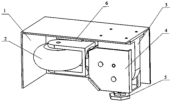
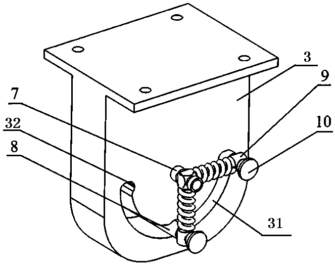
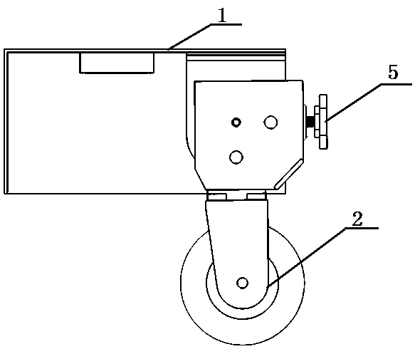
[0026] Such as Figure 1-6 As shown, a roller and foot switchable box support structure of the present invention includes a bottom plate 1 of the box foot part, and the bottom of the bottom plate 1 of the box foot part is fixedly connected with a fixed block 3, and the fixed block 3. A conversion block 4 that can rotate 90° around the central axis is connected through the central axis 7. The conversion block 4 includes two side plates 41 respectively arranged on both sides of the fixed block and two side plates connected with the two side plates. A mounting plate 42, two of the mounting plates are installed on the adjacent two sides of the two side plates, wherein one of the mounting plates is equipped with the universal roller group 2, and the other of the mounting plates is installed with ground A foot bolt 5, a conversion position...


PUM


Abstract

The invention discloses a roller and foundation bolt switching type box supporting structure. The structure comprises a box body foot portion bottom plate, wherein the bottom of the box body foot portion bottom plate is fixedly connected with a fixing block, and the middle of the fixing block is connected with a conversion block capable of rotating around a central shaft by 90 degrees through thecentral shaft; the conversion block comprises two side plates arranged on the two sides of the fixing block and two mounting plates connected with the two side plates, wherein the two mounting platesare mounted on two adjacent sides of the two side plates, a universal roller set is mounted on one of the mounting plates, a foundation bolt is mounted on the other mounting plate, and a conversion and positioning device is arranged between the fixing block and the conversion block. According to the structure, temporary movement and positioning of the box body are facilitated, the operation is simple and convenient, and the reliability is high.

Description

Technical field: [0001] The invention relates to a rolling wheel and foot switching type cabinet support structure, which belongs to the technical field of cabinets. Background technique: [0002] In actual life applications, there are various box-type structural parts in general households, such as refrigerators, storage boxes, shoe cabinets and so on. When these objects are first moved into the house, they need to be easily moved to the position required by the owner. When these objects are too heavy, it is difficult to move them manually. At this time, it can be realized by adding universal rollers at the bottom of these boxes. But when working, it usually needs to stand on the ground stably, and at this time, anchor bolts are needed. And when the use time increases, there will be more dead corners at the bottom of the cabinet that need to be cleaned. At this time, these cabinets need to be removed and restored after cleaning. [0003] Existing cabinets such as refriger...

Claims


Application Information

Patent Timeline
IPC IPC(8): B60B33/06
CPCB60B33/06
Inventor 张艳许修祥陈云飞
Owner SOUTHEAST UNIV
Learn More