Split capsule type cupping device

A split and capsule technology, applied in the direction of suction equipment, etc., can solve the problems of inconvenience, need for electric energy, and inability to move with you, and achieve the effect of simple and convenient operation, compact structure, and scientific design

Inactive Publication Date: 2009-08-12
朱惠芬
View PDF0 Cites 0 Cited by
  • Summary
  • Abstract
  • Description
  • Claims
  • Application Information

AI Technical Summary

Problems solved by technology

[0002] There are two main types of cupping in the prior art. One is traditional cupping. The so-called cupping is to use the combustion of alcohol gas in the tank to expand the air and reduce the density, and then instantly buckle the mouth of the tank on the skin of the human body. When shrinking, the volume shrinks to generate negative pressure to suck the skin; the second is to generate negative pressure by mechanical pumping, that is, a vacuum pump is formed by using a piston and a cylinder. Cupping also produces negative pressure to suck the skin. There are electric and manual vacuum pumps. The disadvantage of the electric pump is that it needs electric energy and cannot be moved with you. Catheter connection is required between the pumps. It is very inconvenient to place cupping at multiple positions on a patient and repeatedly pull and connect the airway tube. Moreover, pulling the piston once cannot generate enough negative pressure, thus affecting the therapeutic effect.

Method used


Image

  • Split capsule type cupping device
  • Split capsule type cupping device
  • Split capsule type cupping device

Examples


Embodiment

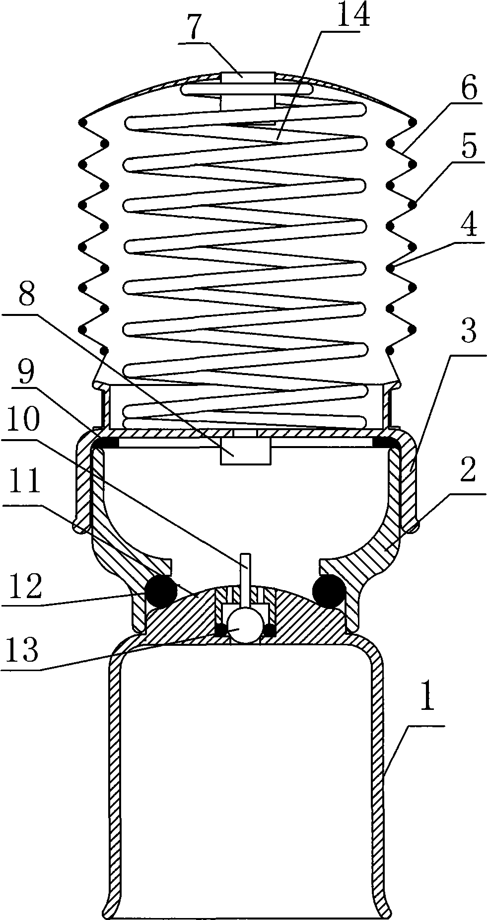
[0016] Embodiment: As shown in the accompanying drawings, the cupping device of the present invention is very simple and convenient to manufacture. Each component is processed by injection molding as shown in the accompanying drawings, and then assembled together. The bellows can be made of rubber or plastic film or rubberized fiber cloth. The manufacturing process is a known technology.

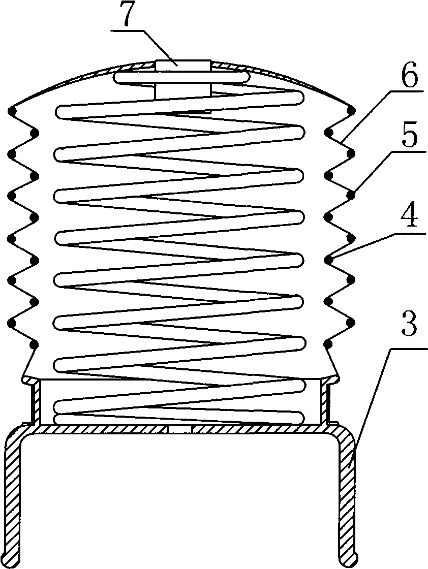
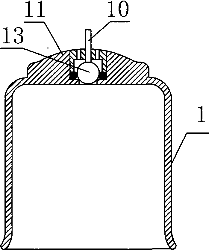
[0017] The use of the cupping device of the present invention is more simple and convenient. When in use, the opening of the split tank is buckled on the skin of the acupuncture point, and the boss on the top of the split tube is plugged together with the socket at the lower end of the bellows type negative pressure pump. , the spring in the bellows is compressed, the gas in the bellows is discharged from the one-way valve, and then released, the one-way valve is closed, the spring expands and the bellows expands, the volume inside the bellows becomes larger, generating negative pressure, an...


PUM


Abstract

The invention provides a split capsule type cupping device composed of a split pot, a ripple barrel type subpressure pump and a necking port; wherein, the split pot is arranged at the bottom of the ripple barrel type subpressure pump by the necking port, the ripple barrel type subpressure pump is composed of a ripple barrel, a birdmouth, a spring, an internal sizing ring and an external sizing ring; the lower end of the ripple barrel is connected with the upper end of the birdmouth by sealing, the lower end of the spring is connected with the upper end of the birdmouth; the upper end of the spring is located in the ripple barrel, the internal sizing ring is arranged in a ring groove of the internal wall of the ripple barrel, the external sizing ring is arranged in an external ring groove of the ripple barrel, a big mouth of the necking port is in cuttage grafting with an end opening of the birdmouth, a small mouth at the lower end of the necking port is in cuttage grafting with a convex plate at the top part of the split pot. Compared with the prior art, the cupping device of the invention is characterized by rational design, simple structure, safety and reliability, small volume, convenient use and portability, thus enjoying great value in promotion and application.

Description

technical field [0001] The invention relates to a medical and health care device, in particular to a split capsule type cupping device. Background technique [0002] There are two main types of cupping in the prior art. One is traditional cupping. The so-called cupping is to use the combustion of alcohol gas in the tank to expand the air and reduce the density, and then instantly buckle the mouth of the tank on the skin of the human body. When shrinking, the volume shrinks to generate negative pressure to suck the skin; the second is to generate negative pressure by mechanical pumping, that is, a vacuum pump is formed by using a piston and a cylinder. Cupping also produces negative pressure to suck the skin. There are electric and manual vacuum pumps. The disadvantage of the electric pump is that it needs electric energy and cannot be moved with you. The pumps need to be connected by catheters. It is very inconvenient to place cupping at multiple positions on a patient and ...

Claims


Application Information

Patent Timeline
Patent Type & Authority Applications(China)
IPC IPC(8): A61M1/00
Inventor 朱惠芬
Owner 朱惠芬
Why Eureka
Try Eureka