A distributed collaborative absorption method for braking energy in urban rail transit

A technology for urban rail transit and braking energy, which is applied in the field of distributed and collaborative absorption of urban rail transit braking energy, can solve the problems of no effective recycling, large short-term feedback current, and increased installation cost, so as to reduce feedback The probability of urban power grid and the effect of reducing power shock

A technology for urban rail transit and braking energy, which is applied in the field of distributed and collaborative absorption of urban rail transit braking energy, can solve the problems of no effective recycling, large short-term feedback current, and increased installation cost, so as to reduce feedback The probability of urban power grid and the effect of reducing power shock

CN110816367BActive Publication Date: 2021-03-26CHINA CREC RAILWAY ELECTRIFICATION BUREAU GRP

Image

  • A distributed collaborative absorption method for braking energy in urban rail transit
  • A distributed collaborative absorption method for braking energy in urban rail transit
  • A distributed collaborative absorption method for braking energy in urban rail transit

Examples


Embodiment Construction

[0047] The present invention will be further described below in conjunction with the accompanying drawings. It should be noted that this embodiment is based on the technical solution, and provides detailed implementation and specific operation process, but the protection scope of the present invention is not limited to the present invention. Example.

[0048] This embodiment provides a method for distributed and coordinated absorption of urban rail transit braking energy.

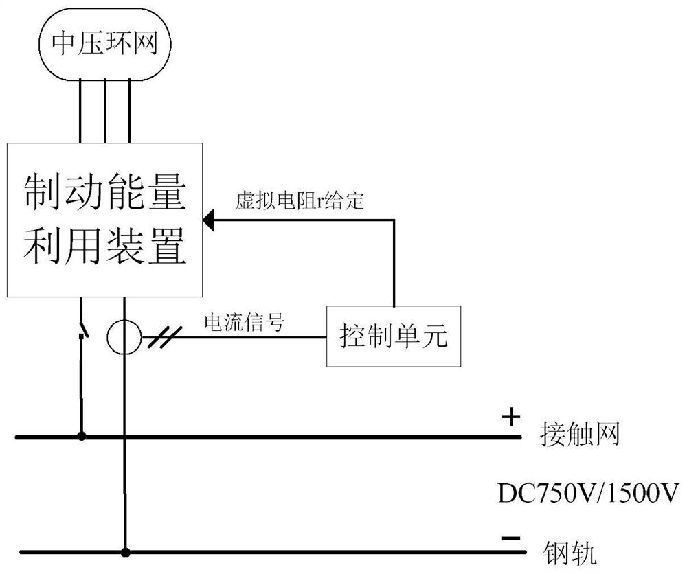
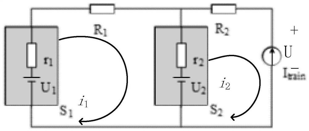
[0049] In this example, the system block diagram of each station is as follows figure 2 shown. During the electrical braking process of the train, the braking energy will be fed back to the traction substation equipped with a braking energy utilization device. Since the catenary between the substation and the substation has impedance, it is farther away from the two sides of the train The substation only absorbs very little braking energy, and most of the energy is absorbed by the adjacent substations on...


PUM


Abstract

The invention discloses a distributed cooperative absorption method for urban rail transit braking energy. Braking energy utilization devices of adjacent stations are triggered to be put into operation by controlling the absorption voltage of a traction substation braking energy utilization device, so that the regenerative braking peak power of a train which enters a station can be jointly absorbed by the energy utilization devices of the multiple adjacent stations, the power impact on a single station is reduced, better utilization of the regenerative braking energy in a subway system is facilitated, and the probability of transmitting electric energy back to an urban power grid is reduced.

Description

technical field [0001] The invention relates to the technical field of urban rail transit, in particular to a method for distributed and coordinated absorption of braking energy of urban rail transit. Background technique [0002] At present, the traction power supply system of urban rail transit mainly consists of two parts, a traction substation 101 and a traction network 100 . The DC traction substation 101 rectifies the three-phase high-voltage AC 10kV / 35kV into DC750V / 1500V suitable for train operation. The feeder 102 sends the DC power from the traction substation to the catenary and the third rail. The catenary 103 is a power supply line erected along the running rail 104 of the train, and the train obtains power through the contact between the pantograph and the catenary (the third rail). The running rail 104 constitutes a part of the traction power supply circuit, and the return line 105 guides the rail return to the traction substation. Structural diagram such a...

Claims


Application Information

Patent Timeline
26 Mar 2021
Publication
CN110816367B
IPC
B60M3/06; B60M3/00
CPC
B60M3/00; B60M3/06
Inventors
白锡彬; 郭戈