
Ground roller heavy load transport line

A technology of transportation lines and floor rollers, applied in the directions of transportation, packaging, conveyors, etc., can solve the problems of sliding friction between rollers and conveyor belts, affecting the delivery speed of goods, and limiting pressure, avoiding direct pressure and improving carrying capacity. effect with durability

Pending Publication Date: 2020-02-21
XINHAI IND BELTING
View PDF0 Cites 0 Cited by
  • Summary
  • Abstract
  • Description
  • Claims
  • Application Information

AI Technical Summary

Problems solved by technology

[0002] In the existing conveying equipment, there are often pressure restrictions, and it is impossible to convey a large number of heavy goods
The main reason is that the conveyor belt of general conveying equipment is directly covered on the ground roller, and the transportation of heavier goods will cause greater pressure on the roller or wear strip
For long-term transportation of heavy goods, the rollers or wear strips cannot bear such a large load, which will cause the friction between the rollers and the conveyor belt to decline, affecting the transmission speed of the goods, and cannot meet the needs of modern industrial production

Method used


Image

  • Ground roller heavy load transport line
  • Ground roller heavy load transport line
  • Ground roller heavy load transport line

Examples


Embodiment Construction

[0025] Below, the present invention will be further described in conjunction with the accompanying drawings and specific implementation methods. It should be noted that, under the premise of not conflicting, the various embodiments described below or the technical features can be combined arbitrarily to form new embodiments. .

[0026] In describing the present invention, it is to be understood that the terms "upper", "lower", "front", "rear", "left", "right", "horizontal", "vertical", "top", The orientation or positional relationship indicated by "inner", "outer", etc. is based on the orientation or positional relationship shown in the drawings, and is only for the convenience of describing the present invention and simplifying the description, rather than indicating or implying that the referred device or element must have Certain orientations, constructed and operative in certain orientations, therefore are not to be construed as limitations of the invention. In addition, ...


PUM


Abstract

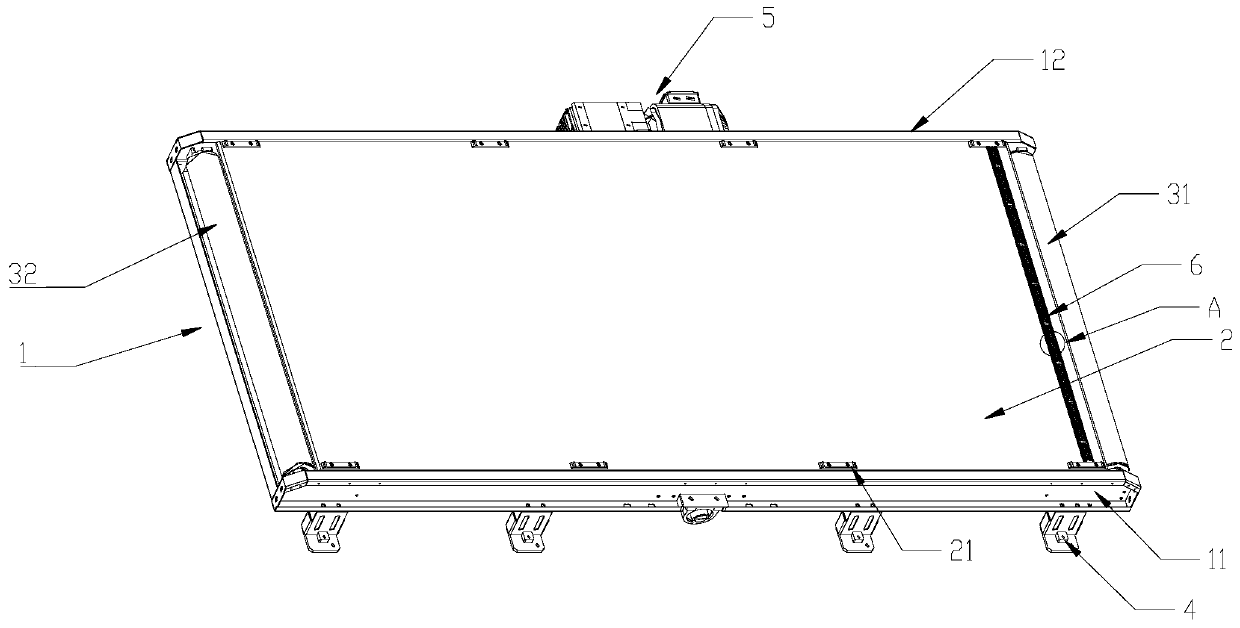
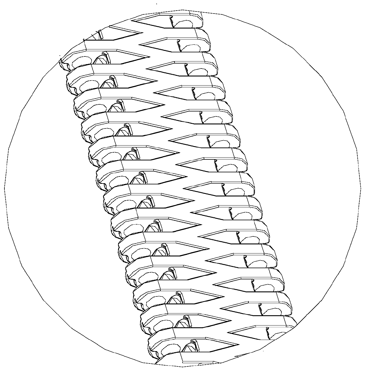
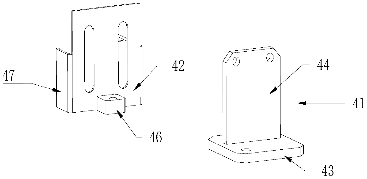
The invention discloses a ground roller heavy load transport line. The ground roller heavy load transport line comprises a support, a rotation shaft rotatably connected with the support and a conveyorbelt arranged on the rotation shaft in a winding mode, wherein the support comprises a first side plate and a second side plate which are relatively parallel, the rotation shaft comprises a transmission shaft and a roller, the transmission shaft is transversely installed between the first side plate and the second side plate, the roller comprises a first roller and a second roller, the first roller and the second roller are respectively and transversely installed at two ends of the first side plate and two ends of the second side plate, a drive assembly is arranged on the support, the drive assembly drives the transmission shaft to drive the conveyor belt to move around the first roller and the second roller, a bearing plate in a flat plate shape is arranged between the conveyor belt andthe support, and the bearing plate is fixed between the first side plate and the second side plate, and supports the conveyor belt. By adding the bearing plate, a load from the conveyor belt to the roller or a wear-resisting strip in the transport process is reduced, and carrying capacity and durability of the transport line are improved.

Description

technical field [0001] The invention relates to the field of conveying equipment, in particular to a ground roller heavy-duty conveying line. Background technique [0002] In the existing conveying equipment, there are often pressure-bearing restrictions, and it is impossible to convey a large number of heavy goods. The main reason is that the conveyor belt of general conveying equipment is directly covered on the ground rollers, and the transportation of heavier goods will cause greater pressure on the rollers or wear strips. For long-term transport of heavy goods, the rollers or wear strips cannot bear such a large load, which will cause the friction between the rollers and the conveyor belt to decline, affecting the transmission speed of the goods, and cannot meet the needs of modern industrial production. Contents of the invention [0003] In order to overcome the deficiencies in the prior art, the object of the present invention is to provide a heavy-duty conveyor li...

Claims


Application Information

Patent Timeline
Patent Type & Authority Applications(China)
IPC IPC(8): B65G23/44
CPCB65G23/44
Inventor 洪健荣
Owner XINHAI IND BELTING
Learn More