Variable angle cutting bit retaining assembly

A technology of cutting head and holder, applied in the direction of slitting machinery, cutting machinery, roads, etc., can solve the problem that the angle of attack cannot be changed

Inactive Publication Date: 2016-01-13
SANDVIK INTELLECTUAL PROPERTY AB
View PDF16 Cites 3 Cited by
  • Summary
  • Abstract
  • Description
  • Claims
  • Application Information

AI Technical Summary

Problems solved by technology

Traditional pick holders or mounts hold the pick at a predetermined angle of attack and do not currently allow the operator to easily change the angle

Method used


Image

  • Variable angle cutting bit retaining assembly
  • Variable angle cutting bit retaining assembly
  • Variable angle cutting bit retaining assembly

Examples


Embodiment Construction

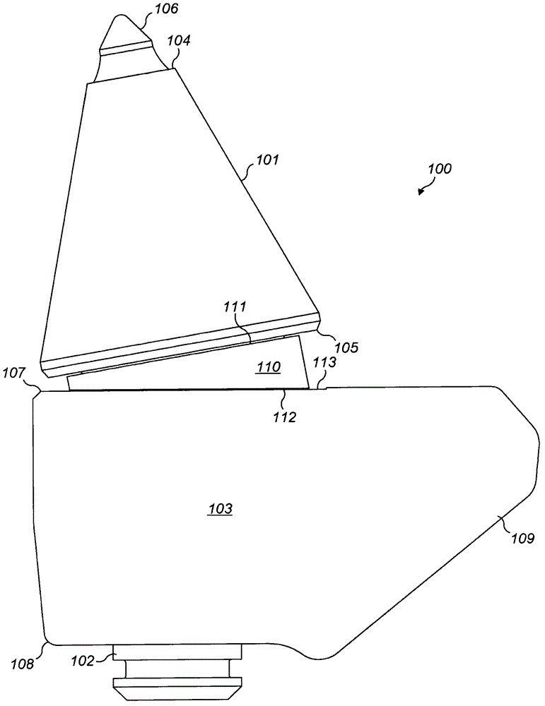
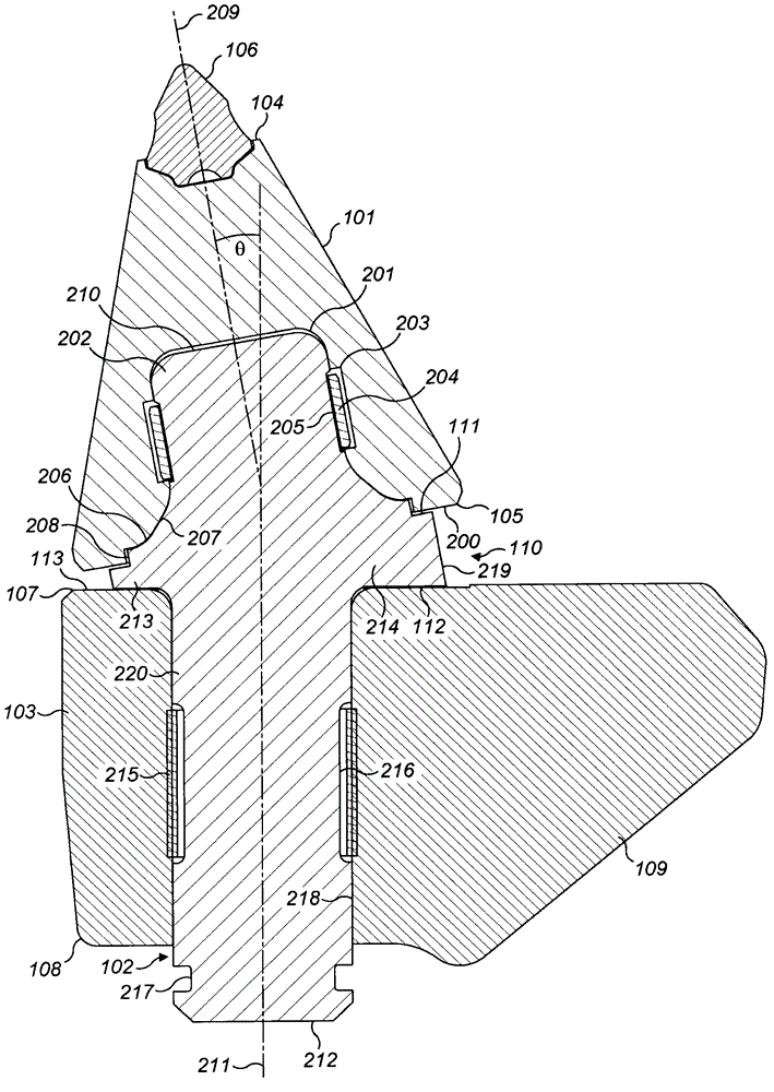
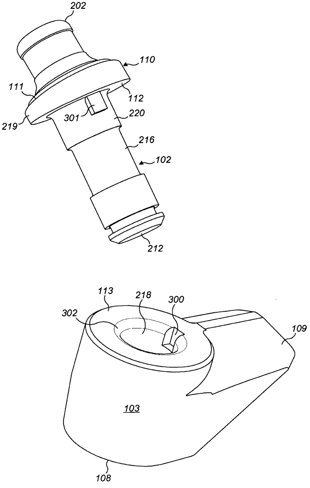
[0026] refer to figure 1 , the cutting head assembly 100 is adapted to be mounted at the outer surface of a rotatable cutting head (or drum) of a cutting machine (not shown). The assembly 100 comprises a cutting head 101 releasably and rotatably mounted at a cutting head holder 103 via an elongate adapter 102 which is correspondingly releasably mounted at a cutting head holder body 103 . The cutting head 101 includes a generally conical profile having a front end 104 to which a cutting tip 106 is mounted and a rear end 105 mounted at a front end 107 of a holder body 103 . The stand body 103 is mounted at the cutting head (or drum) via a mounting flange 109 protruding laterally from one side of the stand body 103 . Shoulder 110 projects radially outward from adapter 102 and includes a generally wedge-shaped configuration. The shoulder 110 includes: a forward facing annular surface 111 positioned to contact the cutting head rear end 105; and a rearward facing annular surface 112...


PUM


Abstract

A cutting bit retaining assembly for mounting a cutting bit at a cutting machine. The assembly comprises a holder body to receive a shank like adaptor with a cutting bit demountable at one end of the adaptor. An annular shoulder is provided at the cutting bit mounting end of the adaptor having a wedge configuration so as to mount the cutting bit at a tilted angle relative to the shank of the adaptor to provide a desired cutting bit attack angle.

Description

technical field [0001] The present invention relates to a cutting bit retention assembly for mounting a cutting bit at a cutting machine, and in particular, but not exclusively, to an assembly configurable to vary the angle of attack of the cutting bit. Background technique [0002] Rock cutting and excavating machines have been developed for a variety of specific applications including: mining, trenching, tunneling, foundation drilling, road milling, and the like. Typically, a drive body or drill bit in the form of a rotatable drum includes a plurality of replaceable cutting heads that provide points of contact for the material or face. [0003] For example, a mobile mining machine includes a rotatable cutting head, wherein the cutting head is arranged on a rotating drum. As the cutting heads contact the surface of the rock, they occasionally break and inevitably wear, resulting in reduced cutting efficiency and requiring replacement. Therefore, it is desirable to mount t...

Claims


Application Information

Patent Timeline
IPC IPC(8): E21C35/19E21C35/18B28D1/22E01C23/088
CPCE21C35/197B28D1/188E21C35/18E21C35/19
Inventor 乔·法代阿尔弗雷德·拉默
Owner SANDVIK INTELLECTUAL PROPERTY AB
Why Eureka
Try Eureka