
Steel wire guard bar

A technology of guardrail and steel wire, applied in the field of rope devices, can solve the problems of high reconstruction cost, low work efficiency, inconvenient fixing, etc., and achieve the effects of small workload, high work efficiency and low change cost

Inactive Publication Date: 2020-02-21
徐州道亨钢绳索具有限公司
View PDF5 Cites 2 Cited by
  • Summary
  • Abstract
  • Description
  • Claims
  • Application Information

AI Technical Summary

Problems solved by technology

However, it is inconvenient to fix the steel wire spacing between the fixed plates, so every time the spacing needs to be adjusted, the steel wire guardrail is completely disassembled and then rebuilt
In this way, the workload is heavy, the work efficiency is low, and at the same time, the transformation cost is high

Method used


Image

  • Steel wire guard bar
  • Steel wire guard bar

Examples


Embodiment Construction

[0017] The technical solutions of the present invention will be clearly and completely described below in conjunction with the accompanying drawings. Apparently, the described embodiments are some of the embodiments of the present invention, but not all of them. Based on the embodiments of the present invention, all other embodiments obtained by persons of ordinary skill in the art without making creative efforts belong to the protection scope of the present invention.

[0018] In the description of the present invention, it should be noted that the terms "center", "upper", "lower", "left", "right", "vertical", "horizontal", "inner", "outer" etc. The indicated orientation or positional relationship is based on the orientation or positional relationship shown in the drawings, and is only for the convenience of describing the present invention and simplifying the description, rather than indicating or implying that the referred device or element must have a specific orientation, ...


PUM


Abstract

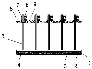
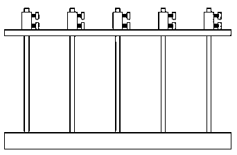
The invention discloses a steel wire guard bar. The steel wire guard bar comprises a lower fixed seat and an upper fixed seat. A sliding groove is formed in the top end of the lower fixed seat. Sliding blocks are arranged in the sliding groove, and a positioning block is arranged between every two sliding blocks. Through holes are formed in the upper fixed seat, and steel wire ropes are arranged between the lower fixed seat and the upper fixed seat. One end of each steel wire rope is fixedly connected with the top end of the corresponding sliding block, and fixed sleeves are arranged at the other ends of the steel wire ropes. The steel wire ropes penetrate through the fixed sleeves to be connected with the fixed sleeves through fixed rods. According to the steel wire guard bar, when the interval between the steel wires is changed, the steel wire guard bar does not need to be demounted, remolding is not needed, only the through holes corresponding to the sliding blocks need to be changed, and the changing mode is small in workload and high in work efficiency. Meanwhile, the change cost is low. The steel wire guard bar is easy to use, convenient to mount, better in practicality, simple in structure, low in manufacturing cost and capable of being widely popularized.

Description

technical field [0001] The invention relates to the technical field of rope devices, in particular to a steel wire guardrail. Background technique [0002] The steel wire guardrail is a kind of guardrail connected by steel wire between the upper and lower fixed plates. The guardrail has simple structure and convenient connection, and can be widely used in protective fields. However, the steel wire spacing between the fixing plates is inconvenient to fix, so the steel wire guardrail is completely dismantled and then rebuilt every time the spacing needs to be adjusted. In this way, the workload is large, the work efficiency is low, and at the same time, the transformation cost is high. [0003] Therefore, a kind of steel wire guardrail is in urgent need of research. Contents of the invention [0004] In order to fully realize the above purpose, a steel wire guardrail is provided aiming at the deficiencies in the prior art. [0005] To achieve the above object, the presen...

Claims


Application Information

Patent Timeline
Patent Type & Authority Applications(China)
IPC IPC(8): E04H17/02E04H17/12
CPCE04H17/02E04H17/12
Inventor 李丽荣
Owner 徐州道亨钢绳索具有限公司
Learn More