High-frequency vibrating vortex generator capable of realizing non-contact driving

An eddy current generator and high-frequency vibration technology, applied in the direction of generating vortices, reducing drag, etc., can solve the problems that the disturbance frequency and disturbance amplitude of the eddy current generator cannot be changed, the limited performance and applicable working conditions, and the lack of dynamic characteristics. Achieve the effect of improving service life, expanding applicable working conditions, and optimizing overall performance

Active Publication Date: 2020-02-25
CHINA ACAD OF AEROSPACE AERODYNAMICS
View PDF5 Cites 0 Cited by
  • Summary
  • Abstract
  • Description
  • Claims
  • Application Information

AI Technical Summary

Problems solved by technology

However, the vortex generators that have been applied in engineering have a common feature: their geometric shape is not adjustable, and they do not have dynamic characteristics, that is, they cannot change the disturbance frequency and disturbance amplitude of the vortex generator, which limits its performance to a large extent. Performance and applicable working conditions

Method used


Image

  • High-frequency vibrating vortex generator capable of realizing non-contact driving
  • High-frequency vibrating vortex generator capable of realizing non-contact driving
  • High-frequency vibrating vortex generator capable of realizing non-contact driving

Examples


Embodiment Construction

[0027] Exemplary embodiments of the present disclosure will be described in more detail below with reference to the accompanying drawings. Although exemplary embodiments of the present disclosure are shown in the drawings, it should be understood that the present disclosure may be embodied in various forms and should not be limited by the embodiments set forth herein. Rather, these embodiments are provided for more thorough understanding of the present disclosure and to fully convey the scope of the present disclosure to those skilled in the art. It should be noted that, in the case of no conflict, the embodiments of the present invention and the features in the embodiments can be combined with each other. The present invention will be described in detail below with reference to the accompanying drawings and examples.

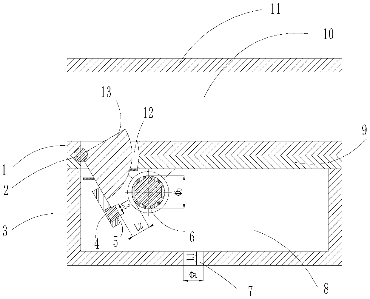
[0028] figure 1 It is a structural schematic diagram of a non-contact driven high-frequency vibration vortex generator provided by an embodiment of the prese...


PUM


Abstract

The invention discloses a high-frequency vibrating vortex generator capable of realizing non-contact driving. The vortex generator comprises a main flow channel part, a vortex component, a driving component and a balance cavity part; the main flow channel part is connected with the balance cavity part; a mounting opening is reserved between the main flow channel part and the balance cavity part; the vortex component is arranged at the mounting opening; the driving component is arranged in a balance cavity of the balance cavity part; the vortex component is driven to vibrate at the high frequency under the action of a magnetic field, then the part, entering a main flow channel of the main flow channel part, of the vortex component is controlled to vibrate at the high frequency, and thus theflow field control is realized. The lower wall surface of the main flow channel part comprises an upper layer and a lower layer; the air flow main flow channel is formed between the upper wall surface of the main flow channel part and the upper layer of the lower wall surface; and the balance cavity is formed between the balance cavity fixing wall of the balance cavity part and the lower layer ofthe lower wall surface. According to the vortex generator, the flow field control performance of the vortex generator is greatly improved.

Description

technical field [0001] The invention relates to a non-contact driven high-frequency vibration eddy current generator, which belongs to the technical field of eddy current generators. Background technique [0002] Flow separation is common in the internal and external flow fields of supersonic / hypersonic vehicles, and flow separation will have a great impact on the flight stability control and structural safety of the aircraft, not only leading to increased drag, decreased lift, and stalled Adverse consequences such as advance can also cause distorted flow field near the engine inlet throat, total pressure recovery decline, engine not starting, etc., and then induce catastrophic accidents. Due to its simple structure and good control effect, the vortex generator is the most common type of flow separation control measures. [0003] A supersonic or hypersonic vehicle flying in the atmosphere will experience a pulsating pressure environment caused by a variety of significant tu...

Claims


Application Information

Patent Timeline
Patent Type & Authority Applications(China)
IPC IPC(8): B64C23/06
CPCB64C23/06Y02T50/10
Inventor 赵永胜杨辉吴军飞
Owner CHINA ACAD OF AEROSPACE AERODYNAMICS
Why Eureka
Try Eureka