
Crankshaft flange coupling device

A coupling and big head technology, which is applied in the field of crankshaft big head coupling devices, can solve the problems of crankshaft flange, crankshaft flange surface damage, labor force, engine assembly, etc., and achieve simple operation, uniform force, and satisfying crankshaft rotation The effect of speed requirements

Pending Publication Date: 2020-02-28
GUANGXI YUCHAI MASCH CO LTD
View PDF0 Cites 3 Cited by
  • Summary
  • Abstract
  • Description
  • Claims
  • Application Information

AI Technical Summary

Problems solved by technology

[0004] The purpose of the present invention is to provide a crankshaft big end coupling device to solve the problem that when the engine is assembled, rotating the crankshaft causes damage to the screw hole and the crankshaft flange surface of the crankshaft flange and one person cannot rotate the crankshaft to assemble the engine, resulting in Difficult problems with high labor force and low efficiency in the assembly process

Method used


Image

  • Crankshaft flange coupling device
  • Crankshaft flange coupling device
  • Crankshaft flange coupling device

Examples


Embodiment Construction

[0028] The present invention will be further described in detail below in combination with specific embodiments. It should be emphasized that the following description is only exemplary and not intended to limit the scope of the invention and its application.

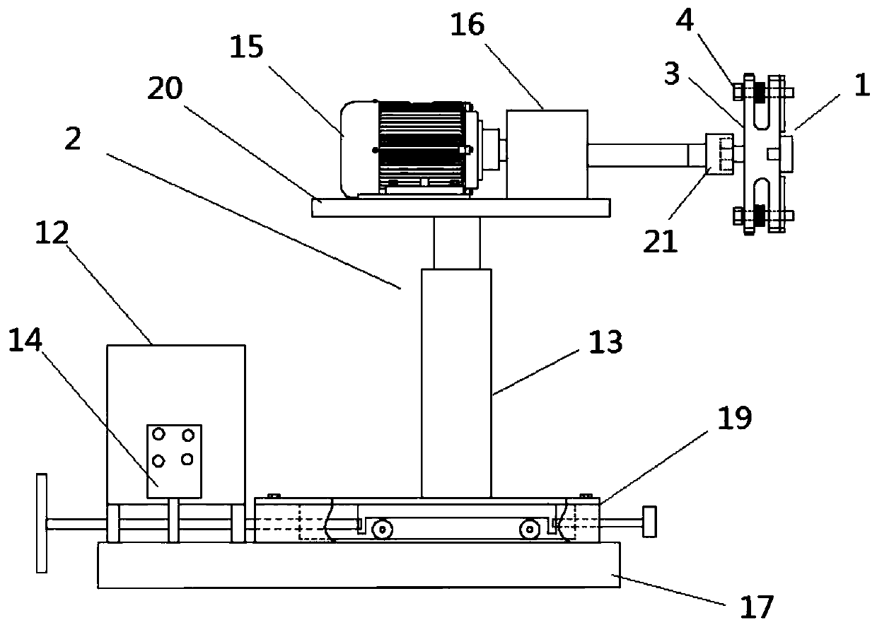
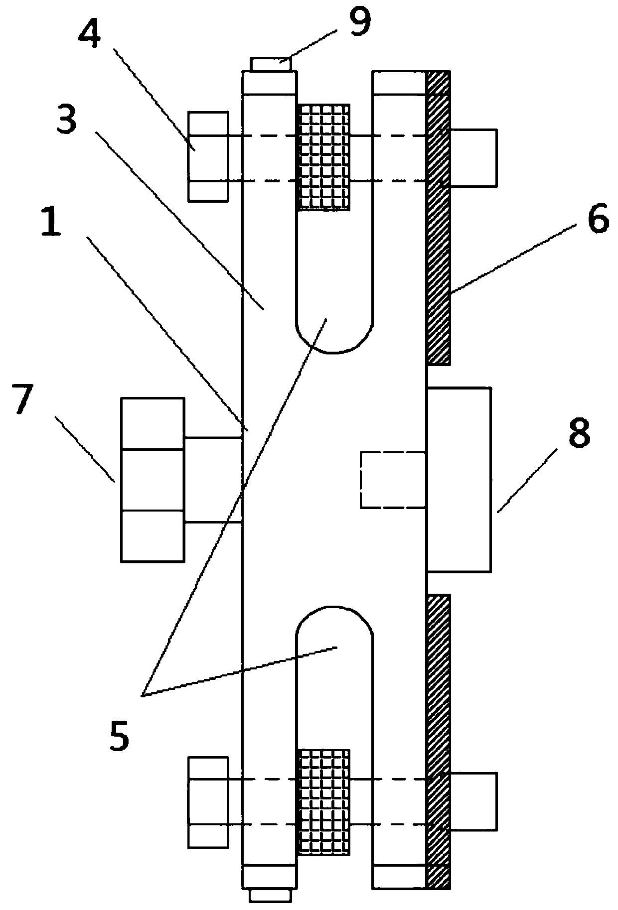
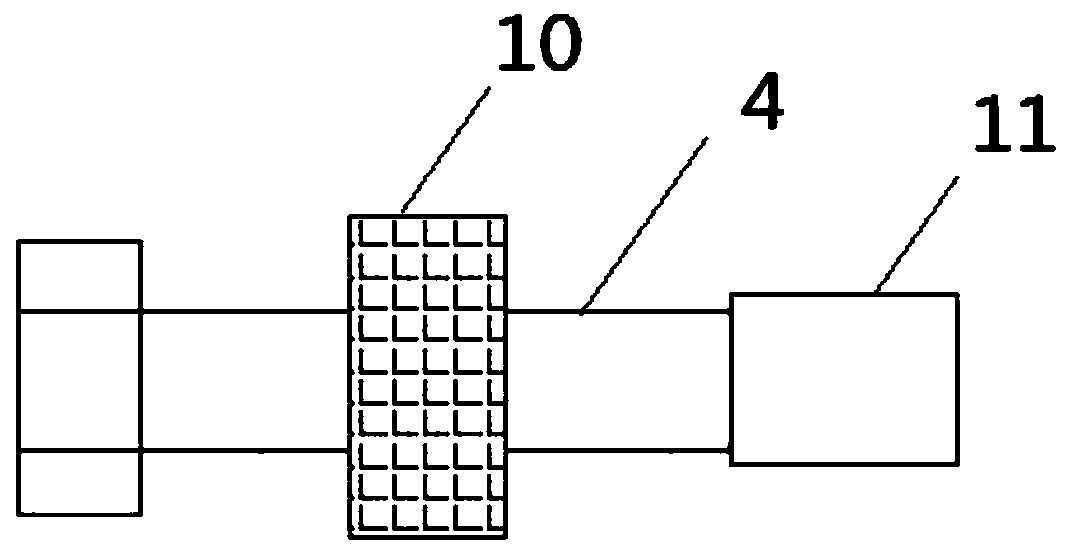
[0029] like Figure 1-9 As shown, a crankshaft large end coupling device is characterized in that: it includes a rotating arm frame assembly 1 and a rotating power group 2; the rotating arm frame assembly 1 includes a rotating arm 3 and a connecting bolt 4; the upper part of the rotating arm 3 and the lower part are respectively provided with symmetrical cross grooves 5, which are used to cooperate with the connecting bolts 4, and U-shaped rubber pads 6 are respectively arranged beside the cross grooves on the right side of the rotating arm 3, which are used to prevent the rotating arm 3 from contacting the crankshaft flange and causing Wear and tear, the U-shaped rubber pad 6 is larger than the cross notch, in order t...


PUM


Abstract

The invention discloses a crankshaft flange coupling device. The device comprises a rotating arm frame assembly and a rotary power set, wherein the rotating arm frame assembly comprises a rotating armand connecting bolts, symmetrical cross grooves are formed in the upper portion and the lower portion of the rotating arm correspondingly, a bolt head is arranged on the left side of the center position of the rotating arm, a detachable circular positioning head is arranged on the right side of the center position of the rotating arm, hand wheels are arranged in the middle of the connecting bolts, connecting threads are arranged on the right portion of the connecting bolts, the connecting bolts are matched with the cross grooves correspondingly, and the rotary power set is matched with the bolt head. According to the crankshaft flange coupling device, the difficult problems of large manpower and low efficiency caused by the fact that when the engine is assembled, the crankshaft is rotatedto cause damage to screw holes of the crankshaft flange and one person cannot rotate the crankshaft to assemble the engine are solved.

Description

technical field [0001] The invention relates to the field of assembly technology, in particular to a crankshaft large end coupling device. Background technique [0002] During the engine assembly process, the engine crankshaft is continuously rotated for assembly and inspection of the internal parts of the engine, so a transitional device is needed to connect with the screw hole of the crankshaft flange (crankshaft big end). At present, when rotating the engine crankshaft, all The two bolts are directly inserted into the screw holes of the crankshaft flange to achieve rotation while applying torque, which will cause damage to the screw holes of the crankshaft flange and affect the quality of the engine. Rotating the crankshaft to assemble the engine causes the problems of large manpower and low efficiency. [0003] The disclosure of the above background technical content is only used to assist in understanding the inventive concepts and technical solutions of the present in...

Claims


Application Information

Patent Timeline
Patent Type & Authority Applications(China)
IPC IPC(8): B25H1/10B25H1/14B25H1/16B25B11/00
CPCB25H1/10B25H1/14B25H1/16B25B11/00
Inventor 吴培柱圣乔乔廖书铖梁绍坚
Owner GUANGXI YUCHAI MASCH CO LTD
Learn More