Manufacturing process of photoelectric liquid level meter

A photoelectric liquid level gauge and manufacturing process technology, which is applied in the field of processing and manufacturing, can solve the problems of lens damage, affecting processing efficiency, and high control precision requirements, and achieve the effects of improving smoothness, uniform connection force, and avoiding damage

Active Publication Date: 2020-07-10
常州松英视液镜有限公司
View PDF10 Cites 0 Cited by
  • Summary
  • Abstract
  • Description
  • Claims
  • Application Information

AI Technical Summary

Problems solved by technology

However, the grinding process requires high control precision for grinding the lens, and it is easy to cause damage to the lens during the grinding process, and the damaged lens can only be discarded, and the lens needs to be replaced for grinding, which increases the processing cost of the lens. Affected processing efficiency

Method used


Image

  • Manufacturing process of photoelectric liquid level meter
  • Manufacturing process of photoelectric liquid level meter
  • Manufacturing process of photoelectric liquid level meter

Examples


Embodiment 1

[0031] Embodiment 1 discloses a manufacturing process of a photoelectric liquid level gauge for the present invention, comprising the following steps:

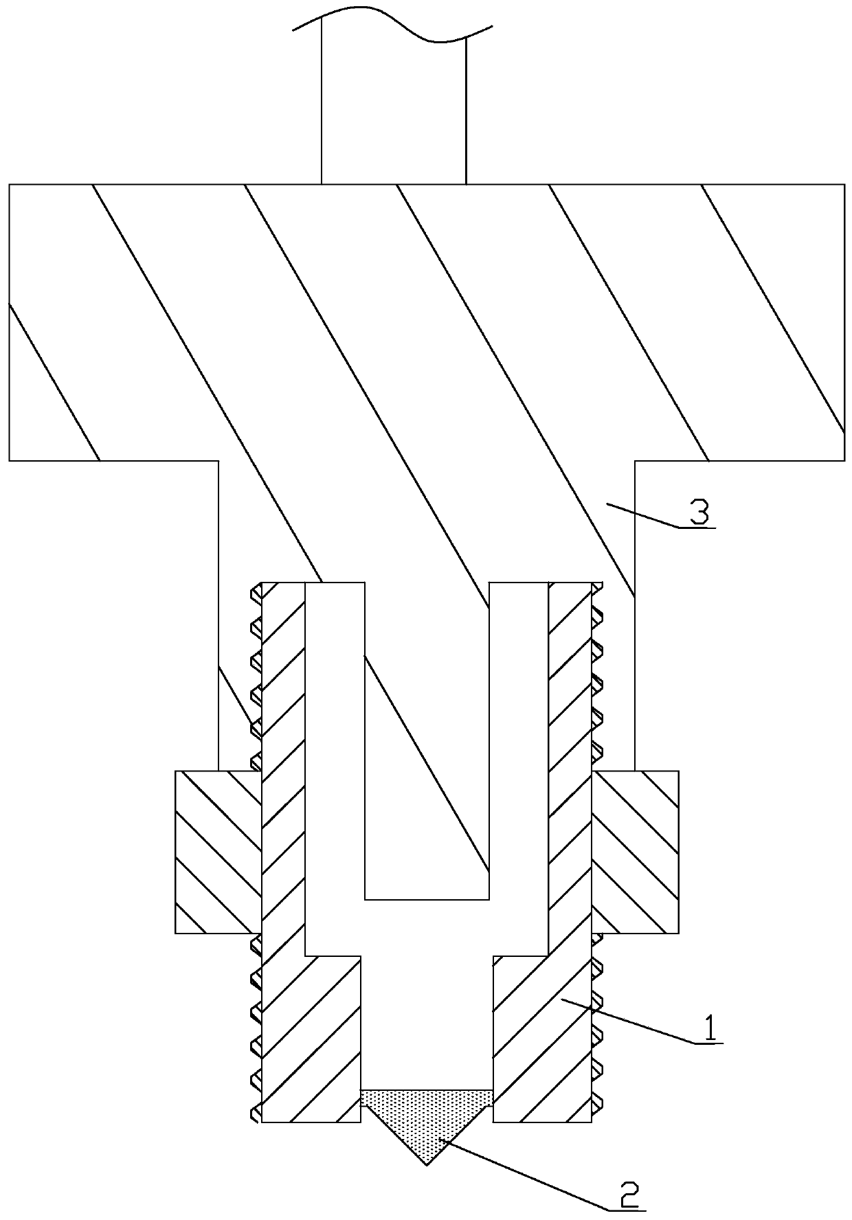
[0032]S1. Process the detection shell 1. Such as figure 2 As shown, the detection housing 1 includes a mounting tube 11 and a mounting nut 12. The mounting tube 11 is in the shape of a round tube with a vertical axis, and the mounting tube 11 is made of 20# steel. The mounting nut 12 is a hexagon head nut. The mounting nut 12 is sheathed on the mounting pipe 11 and fixed to the outer wall of the mounting pipe 11 . The mounting nut 12 is arranged in the middle of the mounting pipe 11 . An installation thread 111 and a fastening thread 112 are provided on the outer wall of the installation pipe 11 , and the installation thread 111 is provided on the lower side of the installation nut 12 for installing the photoelectric liquid level gauge. The fastening thread 112 is provided on the upper side of the mounting nut 12 for mounti...

Embodiment 2

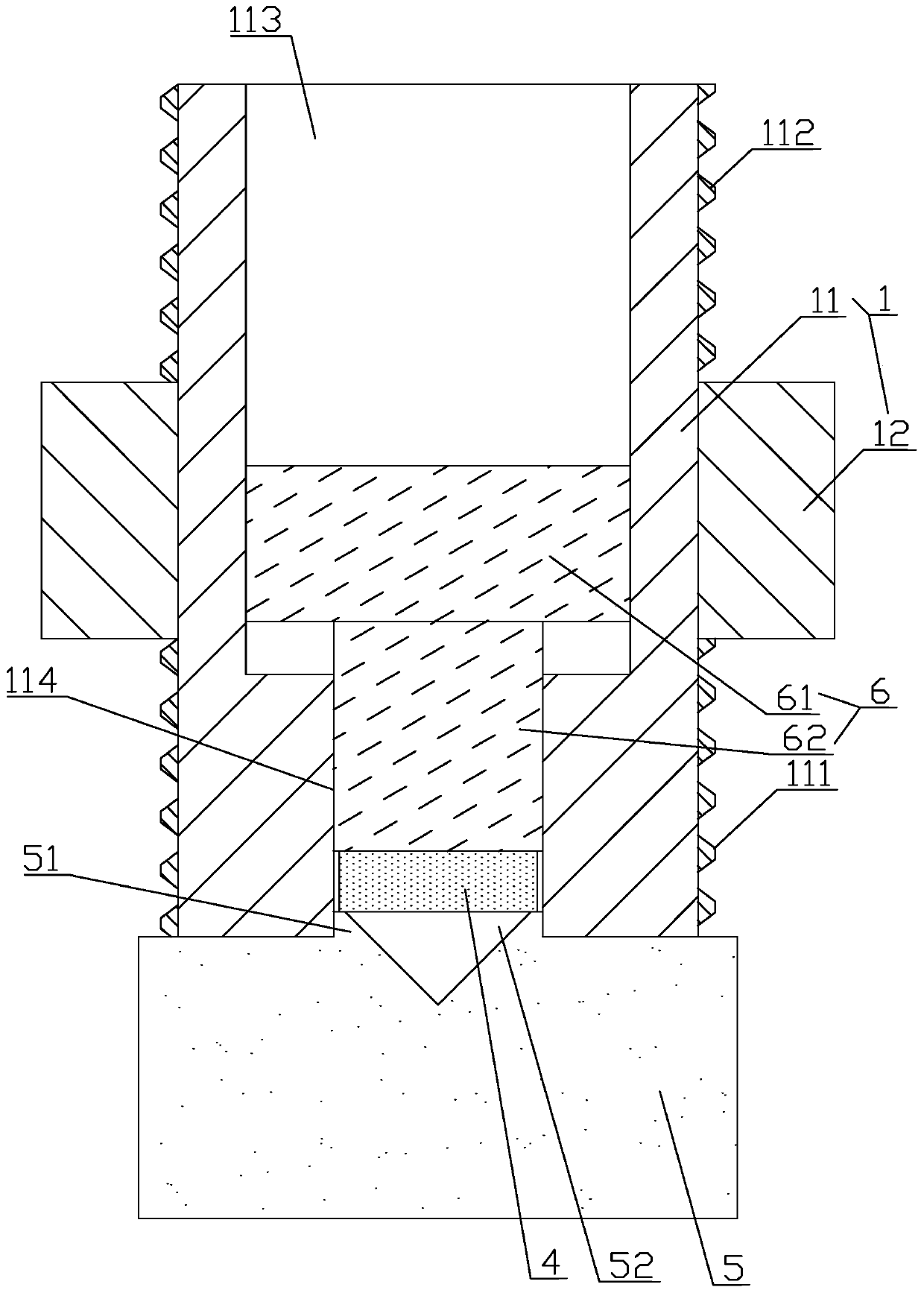
[0040] Embodiment 2 is the manufacturing process of another kind of photoelectric liquid level gauge disclosed by the present invention, such as image 3 As shown, compared with Embodiment 1, the difference of this embodiment is that the bottom surface of the gravity round block 6 is also provided with a ventilation microhole 611, the opening of the ventilation microhole 611 is circular, and the ventilation microhole 611 runs through the gravity round block 6 and is connected with the gravity round block 6. The upper surface of gravity round block 6 is connected.

[0041] In step S4, when the detection housing 1 is heated in the sintering furnace, the glass block 4 is heated and melted, and the gravity round block 61 drives the lower pressure column 62 to move down under the action of gravity. The air between the inner bottom surface of the groove 113 is discharged from the detection housing 1 through the ventilation microhole 611, thereby preventing this part of the air from ...

Embodiment 3

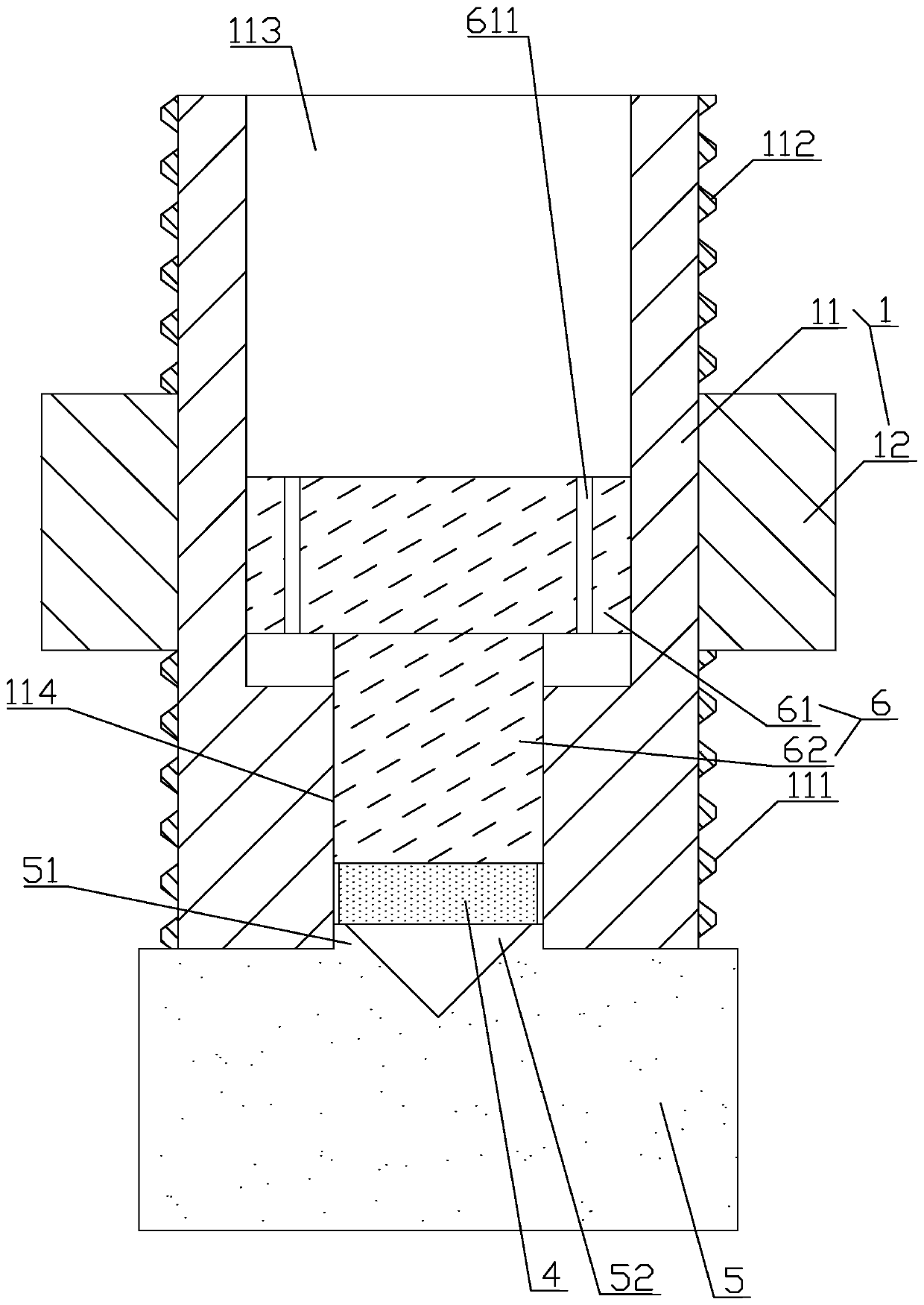
[0042] Embodiment 3 is the manufacturing process of another kind of photoelectric liquid level gauge disclosed by the present invention, such as Figure 4 As shown, compared with Embodiment 2, the difference of this embodiment is that a glass ring 612 is fixed on the bottom surface of the gravity circle block 6, and the glass ring 612 is a circular ring, which is sleeved on the lower pressure column 62, and the inner wall of the glass ring 612 and the lower The side wall of the pressure column 62 is attached, and the outer wall of the glass ring 612 is consistent with the outer diameter of the gravity circle 61 . In addition, the glass ring 612 is made of glass whose melting point is lower than the melting point of the material of the glass block 4 .

[0043] In step S4, when the detection housing 1 is heated in the sintering furnace, the glass block 4 is first heated and melted. At this time, the glass ring 612 has a supporting effect on the gravity circle block 61, and the gl...


PUM


Abstract

The invention relates to a manufacturing process of a photoelectric liquid level meter. The manufacturing process comprises the following steps: S1, machining a detection shell; S2, preparing a glassblock, a graphite support and a pressing block, and cleaning; S3, sequentially placing the pressing block and the glass block into the end of the detection shell and vertically placing the detection shell, and then installing the end of the detection shell on the graphite support; S4, placing the installed detection shell and the graphite support in a sintering furnace to be sintered and heated; S5, taking out the detection shell and the graphite support and cooling; S6, separating the detection shell and the graphite support, taking out the pressing block, and installing and fixing the transmitting and receiving unit and the detection shell; and S7, checking the photoelectric liquid level meter; in the step S2, a conical groove in a conical shape is formed in the surface, connected with the detection shell, of the graphite support, the taper of the conical groove is 2: 1, and the inner wall of the conical groove is polished to be smooth and the volume of the glass block is greater than that of the conical groove. The manufacturing process has the advantages of being low in lens rejection rate and high in machining efficiency.

Description

technical field [0001] The invention relates to the technical field of processing and manufacturing, in particular to a manufacturing process of a photoelectric liquid level gauge. Background technique [0002] The photoelectric liquid level gauge is a new type of contact point liquid level measurement and control device, which uses the principle of reflection and refraction of light at the interface of two different media. The photoelectric liquid level gauge can be detected at a single point, and the TTL compatible digital level signal output is suitable for the production of transportation and military industries. The working principle of the photoelectric liquid level gauge: the product contains a near-infrared light-emitting diode and a photosensitive receiver. The light emitted by the light-emitting diode is guided into the lens at the end of the sensor. When the liquid is immersed in the lens of the photoelectric liquid level switch, the light is refracted Into the l...

Claims


Application Information

Patent Timeline
Patent Type & Authority Applications(China)
IPC IPC(8): G01F23/292C03B19/06
CPCG01F23/292C03B19/06
Inventor 胡英江陈松青陈松涛
Owner 常州松英视液镜有限公司
Why Eureka
Try Eureka