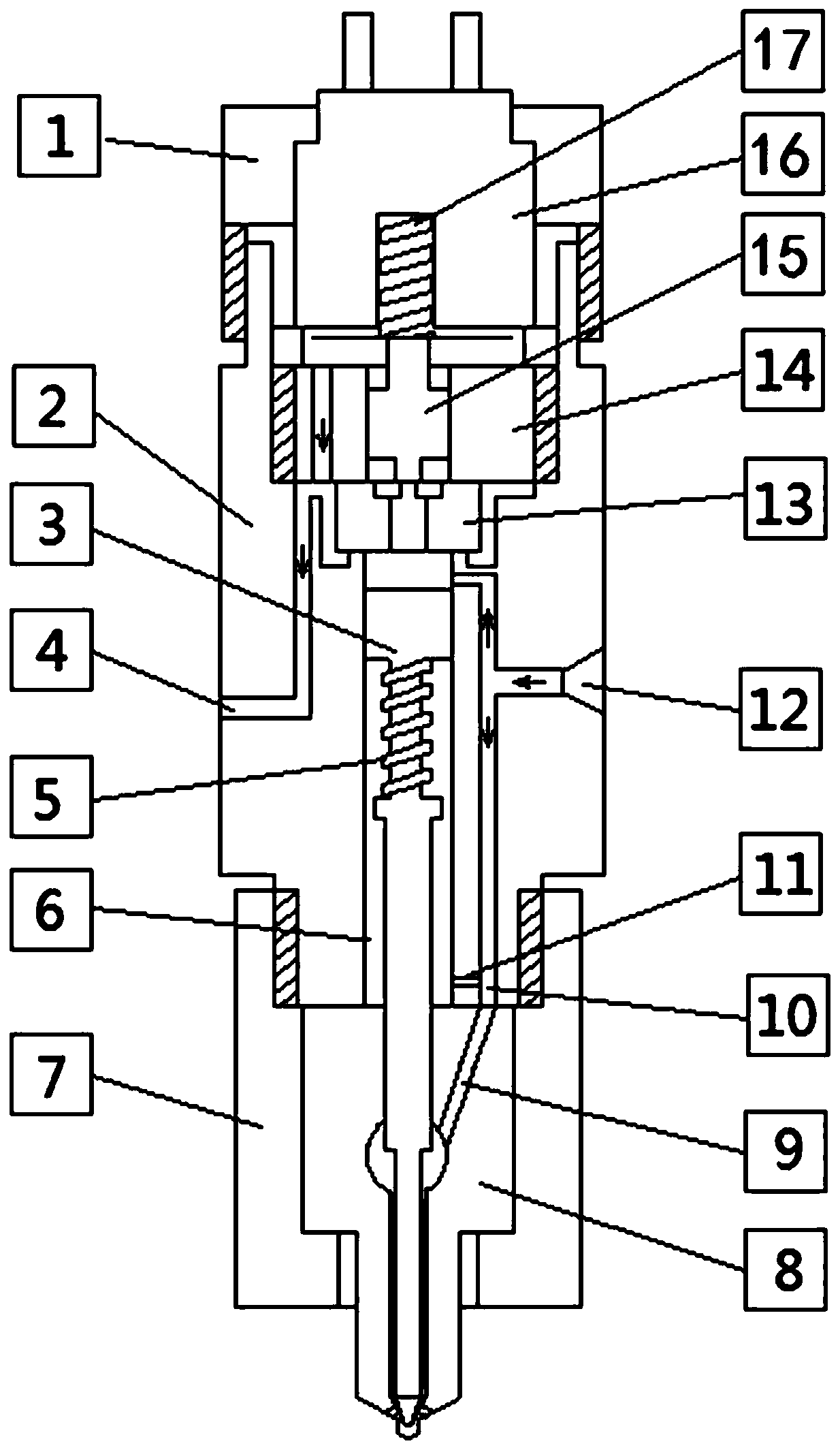
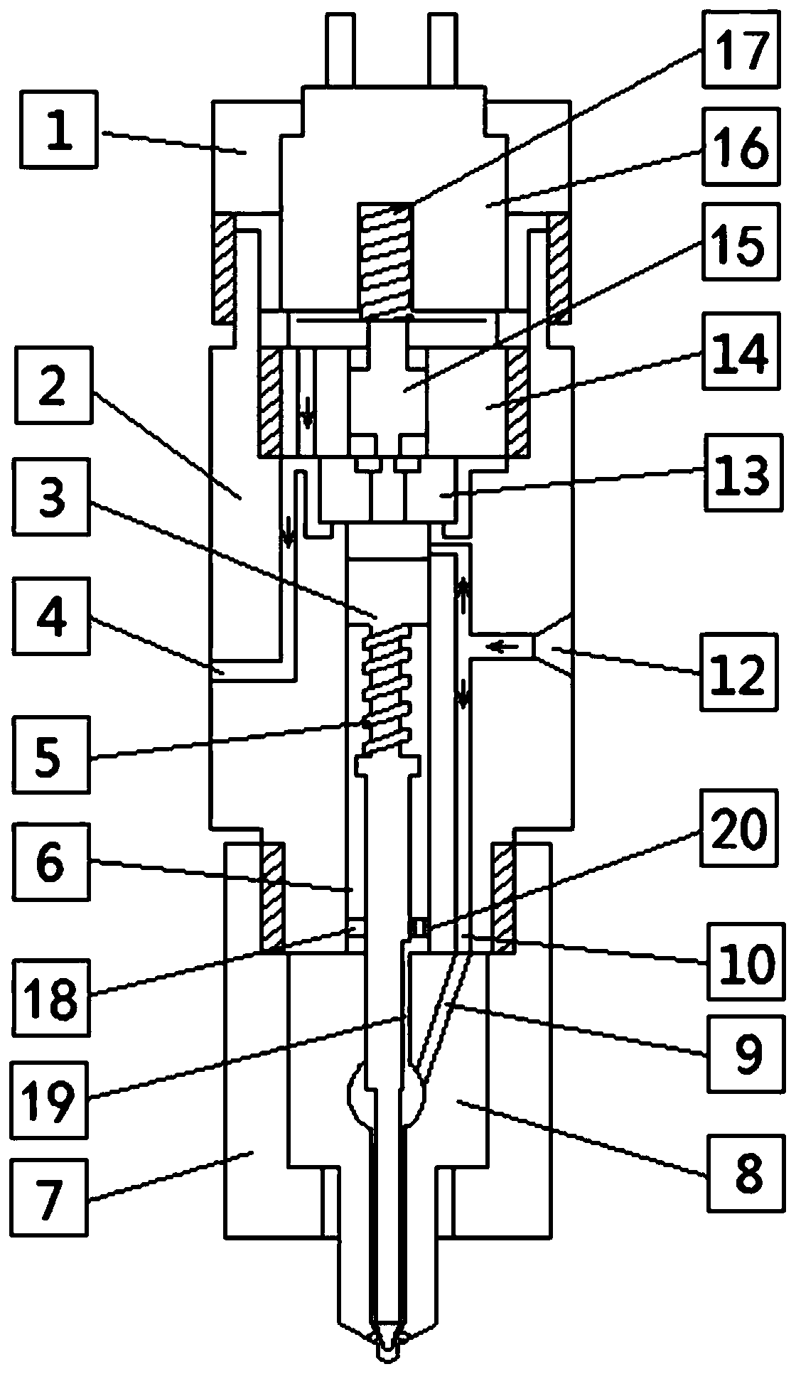
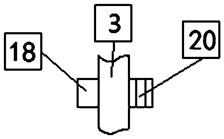
Electrically-controlled pressure-storage oil injector

A fuel injector and pressure accumulating technology, which is applied to machines/engines, fuel injection devices, engine components, etc., can solve problems such as unfavorable engine combustion performance matching, rapid increase in fuel injection rate, and increase in the structural size of the injector body. , to optimize the fuel injection performance, improve the opening power of the needle valve, and reduce the effect of supplementing high-pressure fuel.

Active Publication Date: 2020-02-28
CHINA NORTH ENGINE INST TIANJIN
View PDF7 Cites 2 Cited by
  • Summary
  • Abstract
  • Description
  • Claims
  • Application Information

AI Technical Summary

Problems solved by technology

However, after the volume of the control plunger chamber increases, the structural size of the injector body will increase, and the high-pressure sealing safety of the control plunger chamber also needs to be reconsidered
At the same time, due to the increase in the volume of the control plunger cavity, it is also easy to cause the fuel injection rate to rise too fast at the initial stage of fuel injection, which is not conducive to matching the engine combustion performance.

Method used


Image

  • Electrically-controlled pressure-storage oil injector
  • Electrically-controlled pressure-storage oil injector
  • Electrically-controlled pressure-storage oil injector

Examples


Embodiment Construction

[0027] It should be noted that, in the case of no conflict, the embodiments of the present invention and the features in the embodiments can be combined with each other.

[0028] In describing the present invention, it should be understood that the terms "center", "longitudinal", "transverse", "upper", "lower", "front", "rear", "left", "right", " The orientations or positional relationships indicated by "vertical", "horizontal", "top", "bottom", "inner" and "outer" are based on the orientations or positional relationships shown in the drawings, and are only for the convenience of describing the present invention and Simplified descriptions, rather than indicating or implying that the device or element referred to must have a particular orientation, be constructed and operate in a particular orientation, and thus should not be construed as limiting the invention. In addition, the terms "first", "second", etc. are used for descriptive purposes only, and should not be understood ...


PUM


Abstract

The invention provides an electrically-controlled pressure-storage oil injector. The oil injector comprises an oil injector body and a control plunger rod; a control valve, an armature assembly, a solenoid valve spring, a solenoid valve and first compacting mechanism are sequentially arranged above the oil injector body from bottom to top, the control valve is in pressing connection with the oil injector body through a second pressing mechanism, the control plunger rod is mounted in the oil injector body, and the exterior of the control plunger rod is sleeved with a needle valve spring; and the lower end of the oil injector body is provided with an oil nozzle matching part, an oil inlet channel is arranged in the oil nozzle matching part, the control plunger rod and the valve needle of theoil nozzle matching part are of an integral structure, the needle valve spring presses the valve needle of the oil nozzle matching part on the valve body, the large head of the control plunger rod and the oil nozzle matching part form a control plunger cavity in the oil injector body, and the control plunger cavity communicates with the high-pressure oil inlet channel. According to the electrically-controlled pressure-storage oil injector, the pressure of the control plunger cavity is controlled through throttling holes, so that the effect of improving the opening power of the needle valve and reducing the opening resistance of the needle valve is realized, and therefore the oil injection performance is optimized.

Description

technical field [0001] The invention belongs to the technical field of electronically controlled fuel injectors, in particular to an electronically controlled accumulator fuel injector. Background technique [0002] Conventional electronically controlled fuel injectors are divided into structures with accumulator and structures without accumulator. Generally, a control plunger rod is arranged in the pressure accumulation chamber of an injector with a pressure accumulation structure, and the pressure accumulation structure is also called a control plunger chamber. In general design, the control plunger chamber is directly connected with the high-pressure oil inlet passage, and the control plunger chamber is directly connected with the injector assembly. Since the volume of the oil tank of the injector is smaller than the volume of the control plunger cavity, it can be ignored. On the one hand, the control plunger cavity must control the operation of the needle valve, and on...

Claims


Application Information

Patent Timeline
Patent Type & Authority Applications(China)
IPC IPC(8): F02M47/02F02M51/06F02M61/10F02M61/16F02M63/00F02M61/18
CPCF02M47/027F02M51/061F02M61/10F02M61/16F02M63/0017F02M61/18
Inventor 吴小军陈晓欢高怡奚星孙树平顾娇娇李春辉王国莹张冬梅
Owner CHINA NORTH ENGINE INST TIANJIN
Why Eureka
Try Eureka