
Optical switch loss measurement and calibration method in a distributed optical fiber temperature measuring device

A technology of distributed optical fiber and temperature measuring device, which is applied in the direction of measuring device, heat measurement, thermometer, etc., and can solve the problem of deviation between measured temperature and actual temperature

Active Publication Date: 2021-05-04
XUCHANG XJ SOFTWARE TECH +3
View PDF6 Cites 0 Cited by
  • Summary
  • Abstract
  • Description
  • Claims
  • Application Information

AI Technical Summary

Problems solved by technology

[0009] Aiming at the problem that there is still a certain deviation between the measured temperature and the actual temperature in the existing optical fiber temperature measurement device considering the fiber loss, after research, it is found that in order to realize the economy of optical fiber temperature measurement, an optical switch is often placed in the optical fiber temperature measurement device , realize time-sharing temperature measurement of multiple optical fiber lines

Method used


Image

  • Optical switch loss measurement and calibration method in a distributed optical fiber temperature measuring device
  • Optical switch loss measurement and calibration method in a distributed optical fiber temperature measuring device
  • Optical switch loss measurement and calibration method in a distributed optical fiber temperature measuring device

Examples


Embodiment Construction

[0034] The present invention will be described in further detail below in conjunction with the accompanying drawings.

[0035] Embodiment of the Optical Switching Loss Measurement Method in the Distributed Optical Fiber Temperature Measurement Device of the Present Invention

[0036] The optical switch loss measurement method in the distributed optical fiber temperature measuring device of the present invention comprises the following steps:

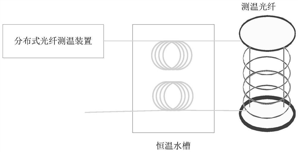
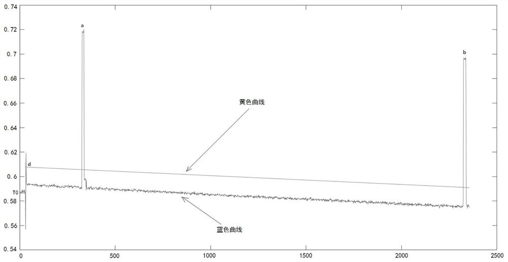
[0037] 1) collecting the Stokes optical signal and the anti-Stokes optical signal at the set temperature at the set position; the distance between the set position and the temperature measurement starting position is l, l>d, where d is The distance between the position of the optical switch in the temperature measurement optical fiber and the starting position of the temperature measurement;

[0038] 2) The collected Stokes optical signal and anti-Stokes optical signal, set temperature and calibration temperature T in step 1) 0 Bring i...


PUM


Abstract

The invention relates to a method for measuring and calibrating optical switch loss in a distributed optical fiber temperature measuring device. The method includes: 1) collecting Stokes light at a position with a distance of 1 from the starting position of temperature measurement at a set temperature signal and the anti-Stokes optical signal, l is greater than the distance between the position of the optical switch and the temperature measurement initial position; 2) according to the temperature demodulation formula and the Stokes optical signal and anti-Stokes optical signal collected in step Tox light signal, calculate the calibration temperature T 0 The ratio of the actual Stokes light signal to the anti-Stokes light signal; 3) according to the calibration temperature T 0 The initial value of the ratio of the two curves of lower Stokes and anti-Stokes light and the ratio calculated in step 2) to obtain the optical switch loss coefficient. The calibration method is: using the above measurement method to obtain the loss coefficient of the optical switch, and using the loss coefficient of the optical switch to correct the calibration curve after the optical switch of the distributed optical fiber temperature measuring device. The invention improves the temperature measurement accuracy of each point along the temperature optical fiber.

Description

technical field [0001] The invention belongs to the field of distributed optical fiber temperature measurement systems, and in particular relates to a method for measuring and calibrating optical switch loss in a distributed optical fiber temperature measurement device. Background technique [0002] The distributed optical fiber temperature measurement device uses the entire temperature measurement optical fiber as a sensor, which can test the real-time temperature of all points along the line. As an important indicator of optical fiber temperature measurement, temperature accuracy requires that all points along the optical fiber must meet the standard requirements. According to the temperature demodulation formula: [0003] [0004] Among them, T is the temperature to be measured at a certain position along the optical fiber, and T 0 is the actual temperature at the calibration position (that is, the calibration fiber), that is, the calibration temperature, K B is Bol...

Claims


Application Information

Patent Timeline
Patent Type & Authority Patents(China)
IPC IPC(8): G01K11/32G01K15/00
CPCG01K11/32G01K15/005
Inventor 郭旭王伟杰毛丽娜王青山牧继清梁武民兰五胜路光辉翟登辉雍明超戚振伟陈磊曾国辉卢声王志成王兆庆
Owner XUCHANG XJ SOFTWARE TECH
Learn More