
A kind of backlight module and display device

A technology of backlight module and display device, which is applied in the direction of identification device, printing device, projection device, etc., can solve the problems of increasing manufacturing cost, and achieve the effect of saving cost and avoiding glue dispensing process

Active Publication Date: 2021-12-03
WUHAN CHINA STAR OPTOELECTRONICS TECH CO LTD
View PDF11 Cites 0 Cited by
  • Summary
  • Abstract
  • Description
  • Claims
  • Application Information

AI Technical Summary

Problems solved by technology

[0005] In order to solve the above technical problems, the present invention provides a backlight module and a display device to solve the problem in the prior art that multiple layers of light-shielding glue are required to prevent light leakage from the blind holes of the display panel, which greatly increases the manufacturing cost. cost

Method used


Image

  • A kind of backlight module and display device
  • A kind of backlight module and display device
  • A kind of backlight module and display device

Examples


Embodiment

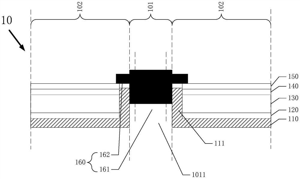
[0032] In this embodiment, the backlight module 10 of the present invention includes an imaging area 101 and a light emitting area 102 surrounding the imaging area 101 .

[0033] like figure 1 As shown, the backlight module 10 further includes an outer frame 110 , a reflective sheet 120 , a light guide plate 130 , a first prism sheet 140 and a second prism sheet 150 .

[0034] The outer frame 110 is disposed in the light-emitting area 102, wherein the outer frame 110 includes a bent portion 111, and the bent portion 111 is upward from the boundary between the imaging area 101 and the light-emitting area 102. Bend to block light.

[0035] The reflective sheet 120 is disposed on the outer frame 110 to reflect light directed toward the outer frame 110 to reduce light loss of the backlight module 10 and improve luminous efficiency.

[0036] The light guide plate 130 is arranged on the reflection sheet 120, and the material of the light guide plate 130 is acrylic or PC material, ...


PUM


Abstract

The invention discloses a backlight module and a display device. The backlight module includes an imaging area and a light-emitting area surrounding the imaging area, and also includes a through hole arranged in the imaging area. The through hole penetrates the outer frame and the reflective sheet , a light guide plate, a first prism sheet and a second prism sheet; a light-shielding structure, which is located on the side of the through hole close to the second prism sheet, and the light-shielding structure extends from the side of the second prism sheet into the through hole, and the light-shielding structure includes a The light-transmitting hole runs through the light-shielding structure along the axial direction of the light-shielding structure. The backlight module and the display device of the present invention provide a through hole in the backlight module to accommodate the camera of the display device. The structure blocks the light of the backlight module to prevent the light in the backlight module from entering the through hole and affecting the imaging of the camera. The light shielding structure adopts the shape of "air eye button", and part of it is set in the through hole. The annular protrusion of the light shielding structure is exposed in the through hole In addition, multiple dispensing processes are avoided, which greatly saves costs.

Description

technical field [0001] The invention relates to the display field, in particular to a backlight module and a display device. Background technique [0002] At present, display devices such as mobile phones and tablet computers often need to reserve space for electronic photosensitive devices such as commonly used front cameras, infrared sensing devices, and fingerprint recognition devices. For example, these photosensitive devices are arranged at the top of the front of the display device, and the corresponding position forms a non-display area, thereby reducing the screen-to-body ratio of the device. [0003] In the prior art, in order to increase the screen-to-body ratio, a high light transmission area can be set up in the display area of ​​the display panel to accommodate the above-mentioned photosensitive device, wherein the high light transmission area can be a channel through which the display panel and the backlight unit are dug through. The hole design can also be a ...

Claims


Application Information

Patent Timeline
Patent Type & Authority Patents(China)
IPC IPC(8): G09F9/00G03B29/00
CPCG03B29/00G09F9/00
Inventor 边家快
Owner WUHAN CHINA STAR OPTOELECTRONICS TECH CO LTD
Learn More