A low rcs phased array antenna and rcs reduction method

A phased array antenna, antenna technology, applied to antennas, antenna unit combinations with different polarization directions, antenna arrays, etc., can solve the problems of destroying aerodynamic layout, increasing the complexity of shape design, and difficult to achieve broadband impedance matching, etc. To achieve the effect of reducing RCS

Active Publication Date: 2021-04-13
UNIV OF ELECTRONICS SCI & TECH OF CHINA
View PDF19 Cites 0 Cited by
  • Summary
  • Abstract
  • Description
  • Claims
  • Application Information

AI Technical Summary

Problems solved by technology

However, broadband impedance matching for radar absorption is difficult to achieve and easily detected by infrared detection devices
The second method is to change the shape of the target. By shaping the antenna, the electromagnetic scattering deviates from the incident direction and reduces the scattering field in the source direction, but this may destroy the aerodynamic layout and increase the complexity of the shape design.

Method used


Image

  • A low rcs phased array antenna and rcs reduction method
  • A low rcs phased array antenna and rcs reduction method
  • A low rcs phased array antenna and rcs reduction method

Examples


Embodiment 1

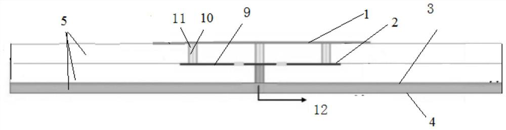
[0033] A phased array antenna with low RCS, including a four-layer structure: a radiation patch layer 1, a cross-shaped feed structure layer 2, a floor layer 3, and a DC feed layer 4, and two adjacent layers are separated by a dielectric substrate 5 open;

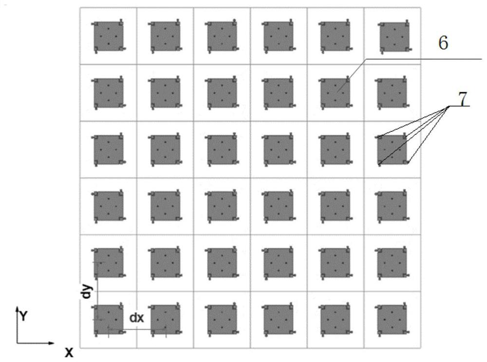
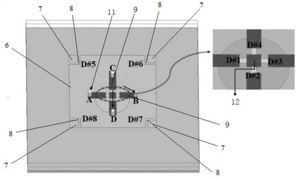
[0034] The phased array antenna includes a plurality of antenna units, and each antenna unit includes a main radiation patch 6, and each radiation patch is provided with four disturbance cut angles 7, and the main radiation patch and the disturbance cut angle are connected by a PIN diode , by controlling the on-off of the PIN diode to realize the switching of the circular polarization mode of the antenna and the switching of the antenna feeding point;

[0035] The cross-shaped feed structure layer includes four horizontal strips 9, each horizontal strip 9 is connected to a vertical column 10 below, and the four horizontal strips are arranged orthogonally in pairs in the horizontal direction, and the clip between two adjacent ...


PUM

PropertyMeasurementUnit
thicknessaaaaaaaaaa

Abstract

The invention provides a phased array antenna with low RCS and a method for reducing RCS thereof. The antenna unit includes a four-layer structure: a radiation patch layer, a cross-shaped feed structure layer, a floor layer, a DC feed layer, and two adjacent layers They are separated by a dielectric substrate; the switching of the circular polarization mode of the antenna and the switching of the antenna feeding point are realized by controlling the on-off of the PIN diode, so as to achieve the effect of equivalent rotation of the antenna unit in the horizontal direction, thereby realizing the antenna unit The scattering field obtains a phase difference of 2 times the rotation angle, that is, 180°; the scattering field of the antenna unit is canceled in the far field and dispersed to a wider angular space, thereby reducing the RCS of the array antenna. The present invention directly affects the scattering of each antenna unit The phase is controlled so that the scattered fields of each array element cannot be coherently added or reflected to a non-threatening angle, thereby reducing the array RCS.

Description

technical field [0001] The invention relates to the field of phased array design, and in particular proposes an effective method for reducing the RCS of the phased array antenna. Background technique [0002] In today's high-tech information warfare, stealth design, as an important part, has important and far-reaching significance for the survivability and combat effectiveness of future weapons and equipment. Anti-enemy camouflage is one of the most important issues in military radar and equipment design. In the electromagnetic wave band, the stealth performance of an object is characterized by its radar cross section (Radar Cross Section, RCS). The smaller the RCS, the easier it is for enemies to hide. Based on the purpose of camouflage, adsorbent materials can be used in the ammunition body, or its physical structure can be modified to achieve the effect of radiation wave deviation, making it impossible for enemy radar to detect it. [0003] Phased array antennas are ind...

Claims


Application Information

Patent Timeline
Patent Type & Authority Patents(China)
IPC IPC(8): H01Q15/24H01Q21/00H01Q21/24
CPCH01Q15/24H01Q21/00H01Q21/24
Inventor 杨鹏尹璐甘育仪张飞
Owner UNIV OF ELECTRONICS SCI & TECH OF CHINA
Why Eureka
Try Eureka