Live indicator lead structure for closed switchgear

A technology of closed switchgear and live indicator, which is applied in the direction of electrical components, busbar/line layout, supervision desk/panel, etc., can solve the problems of unfavorable wiring, easy winding of indicator lead terminal and lead wire, etc., and achieves simple structure and crimping Strong, stable crimping and better effect

Active Publication Date: 2021-05-11
XUJI GRP +3
View PDF8 Cites 0 Cited by
  • Summary
  • Abstract
  • Description
  • Claims
  • Application Information

AI Technical Summary

Problems solved by technology

[0005] The purpose of the present invention is to provide a lead wire structure for a live indicator of a closed switchgear to solve the problem in the prior art that the lead terminal of the live indicator and the outlet terminal are connected by threads, and the lead wire of the lead terminal of the indicator is easily entangled, which is not conducive to wiring.

Method used


Image

  • Live indicator lead structure for closed switchgear
  • Live indicator lead structure for closed switchgear
  • Live indicator lead structure for closed switchgear

Examples


Embodiment 1

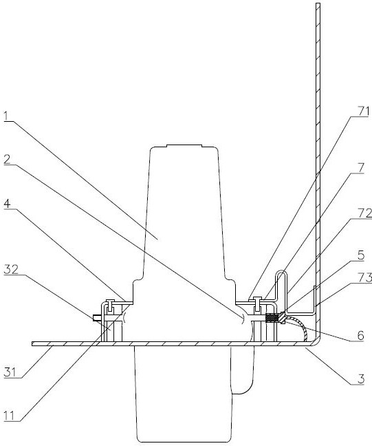
[0043] like figure 1 As shown, the lead structure of the live indicator of the closed switchgear includes an air box 3, an insulating sleeve 1 and an indicator lead terminal 6. The air box wall of the air box 3 includes a sleeve fixing wall 31, and the insulating sleeve 1 is fixed on the sleeve. on the fixed wall 31 .

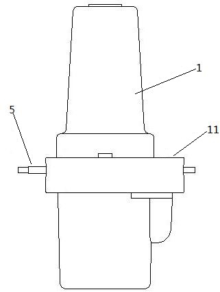
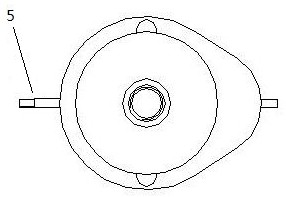
[0044] The insulating sleeve 1 includes a sleeve body, and an induction ring 2 is arranged in the sleeve body, such as figure 2 As shown, the outer circumferential surface of the sleeve body is provided with an outlet terminal 5, and the shape of the outlet terminal 5 is as follows image 3 As shown, the outgoing terminal 5 is conductively connected to the induction ring 2 . The indicator lead terminal 6 is connected to the outgoing terminal 5, and the outgoing terminal 5 and the indicator lead terminal 6 are plug terminals, which are used for fitting and conducting in the form of plugging. The plugging form is as follows: Figure 5 shown. The indicator le...

Embodiment 2

[0049] Embodiment 2 of the lead structure of the live indicator of the closed switchgear provided by the present invention;

[0050] The difference between this embodiment and Embodiment 1 is that, such as Figure 4 As shown, in Embodiment 1, the lead terminal crimping member 7 is used to press the indicator lead terminal 6 connected to the insulating sleeve of each phase. In this embodiment, the lead terminal crimping member 7 is provided with three pieces. Each lead terminal crimping piece 7 corresponds to a phase insulating sleeve respectively.

Embodiment 3

[0052] The difference between this embodiment and Embodiment 1 is that in Embodiment 1, the lead terminal crimping member 7 includes a support plate 73 with an L-shaped structure, and the support plate 73 with an L-shaped structure further includes a support plate part and a connecting plate part. In the example, the lead terminal crimping member 7 is not provided with the L-shaped support plate 73 , and the indicator lead terminal 6 is crimped only by the crimping plate portion 72 .


PUM


Abstract

The invention relates to a live indicator lead wire structure of a closed switchgear. The live indicator lead structure of closed switchgear includes: gas box, insulating bushing and indicator lead terminal, the insulating bushing is fixed on the gas box wall of the gas box; the insulating bushing includes the bushing body, and the bushing body is equipped with In the induction ring, an outlet terminal is provided on the outer peripheral surface of the bushing main body, and the outlet terminal is conductively connected with the induction ring. The indicator lead terminal is connected with a live indicator lead for connecting to the outlet terminal; a lead terminal crimping piece is fixed on the gas box, and the lead terminal crimping piece is pressed on the indicator lead terminal to make the indicator lead terminal Keep connected to the outgoing terminal. The lead terminal crimping piece is used to press on the indicator lead terminal, which can not only keep the indicator lead terminal and the outlet terminal in a connected state, but also solve the problem that the wire of the charged indicator is easy to be entangled.

Description

technical field [0001] The invention relates to a lead structure of a live indicator of a closed switchgear. Background technique [0002] C-GIS metal-enclosed switchgear has the characteristics of small size, compact size, maintenance-free, high reliability, good sealing and insulation performance, and is not affected by external environmental factors in the medium voltage field. have been widely used. The primary circuit of C-GIS metal-enclosed switchgear often realizes the connection between the inside and the outside of the air box through the insulating sleeve. Whether the primary circuit is electrified is usually judged by the electrification indicator connected to the insulating sleeve, so as to provide safety for the operator. ensure. [0003] An induction ring is provided in the main body of the existing insulating sleeve, and an outlet terminal is electrically connected to the induction ring; the insulating sleeve assembly also includes an indicator lead terminal...

Claims


Application Information

Patent Timeline
Patent Type & Authority Patents(China)
IPC IPC(8): H02B1/20H02B15/00H02G3/02
CPCH02B1/20H02B15/00H02G3/02
Inventor 李鹏汤清双史川尹俊强郑瑞广曹志民杨镇宁刘永庆周志洋李豪牛艳红李猛
Owner XUJI GRP
Why Eureka
Try Eureka