
Draw shaft intelligent monitoring device

A technology of intelligent monitoring and equipment, applied in mechanical equipment, TV, color TV, etc., can solve the problems of low monitoring efficiency, stop of conveying operation, danger of monitoring personnel, etc.

Inactive Publication Date: 2020-02-28
南京丰濠网络科技有限公司
View PDF0 Cites 1 Cited by
  • Summary
  • Abstract
  • Description
  • Claims
  • Application Information

AI Technical Summary

Problems solved by technology

[0003] Due to the different sizes of crushed stones produced during the mining process, when the crushed stones fall in the chute, they are easily blocked in the chute, resulting in a decrease in conveying efficiency. As the amount of ore accumulated in the chute increases, it may further lead to transportation operations Stop, in the prior art, when the chute is blocked, it is necessary to manually drill into a so-called observation hole and hold a flashlight to observe the inside of the chute to see where the chute is blocked. This monitoring method will not only bring certain dangers to the monitoring personnel , and the monitoring efficiency is low

Method used


Image

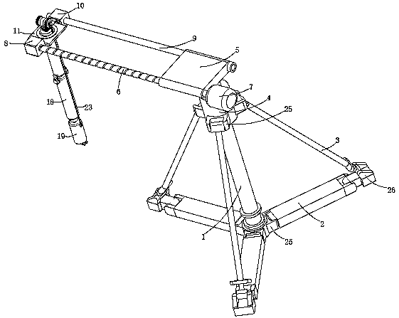
  • Draw shaft intelligent monitoring device
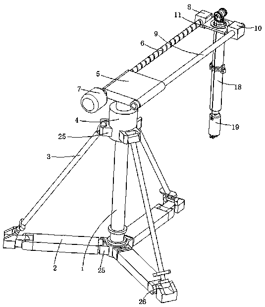
  • Draw shaft intelligent monitoring device
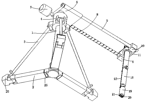
  • Draw shaft intelligent monitoring device

Examples


Embodiment 1

[0034] refer to Figure 1-7 , an intelligent monitoring device for a chute, comprising a vertical rod 1, the outer wall of the bottom end of the vertical rod 1 is rotatably connected with a circumferentially distributed bottom rod 2, the end of the bottom rod 2 away from the vertical rod 1 is rotatably connected with a side support rod 3, and the vertical rod 1 The top of the mounting block 4 is fixedly provided with a mounting block 4, and the end of the side support rod 3 away from the bottom rod 2 is connected to the mounting block 4 in rotation; the top of the mounting block 4 is fixed with a fixed block 5, and one side of the fixed block 5 is rotatably connected with a ball screw 6 , one end of the ball screw 6 is provided with a drive motor 7, the other end of the ball screw 6 is provided with a screw nut 8 used in conjunction with it, and the other side of the fixed block 5 is fixed with a limit rod 9, and the limit rod 9 is arranged in parallel with the ball screw 6, a...


PUM


Abstract

The invention discloses a draw shaft intelligent monitoring device, and belongs to the technical field of draw shaft monitoring devices. The draw shaft intelligent monitoring device comprises a vertical rod, the outer wall at the bottom end of the vertical rod is rotationally connected with a bottom rod distributed circumferentially, and the end, away from the vertical rod, of the bottom rod is rotationally connected with a side supporting rod; a mounting block is fixedly arranged at the top of the vertical rod, and the end, away from the bottom rod, of the side supporting rod is rotationallyconnected with the mounting block; a fixing block is fixedly arranged at the top of the mounting block, a ball screw is rotatably connected to one side of the fixing block, a driving motor is arranged at one end of the ball screw, and a screw nut used in cooperation with the ball screw is arranged at the other end of the ball screw. A camera for monitoring is arranged in a draw shaft from the topof the draw shaft, so that the danger brought to the personnel due to holding a flashlight manually with a hand for monitoring is avoided; and the camera can rotate relative to the inner wall of thedraw shaft, and therefore the inner wall of the draw shaft can be conveniently and accurately monitored.

Description

technical field [0001] The invention relates to the technical field of chute monitoring equipment, in particular to an intelligent chute monitoring device. Background technique [0002] Because the mines are mostly high, in order to improve the transportation efficiency and save costs, a pipeline similar to a well will be opened from top to bottom in some mines, and the ore will be dumped directly from top to bottom. This is the slip shaft, which is mainly used in mining. The ore is conveyed to the next level for crushing or loading, while the transported vehicles wait under the chute, and the fallen ore is transported out by the vehicle. The chute can improve the transportation efficiency on the one hand, and on the other hand, because it is directly dumped vertically, it has a certain Height, so it can play the role of crushing ore to a certain extent. [0003] Due to the different sizes of crushed stones produced during the mining process, when the crushed stones fall in...

Claims


Application Information

Patent Timeline
Patent Type & Authority Applications(China)
IPC IPC(8): H04N7/18H04N5/225H04N5/235F16M11/04F16M11/12F16M11/14F16M11/18
CPCH04N7/18F16M11/043F16M11/12F16M11/14F16M11/18H04N23/56H04N23/74
Inventor 陶莹莹
Owner 南京丰濠网络科技有限公司
Learn More