
High-pressure difference stop valve with U-shaped groove in outlet throttling channel

A technology of throttling channels and concave grooves, which is applied in the field of high pressure differential cut-off valves, can solve problems such as short service life, affect the safety of boiler use, and unsatisfactory effects, and achieve the effects of reducing fluid velocity, improving overall sealing performance and service life

Pending Publication Date: 2020-03-06
SUFA TECH IND CNNC
View PDF0 Cites 0 Cited by
  • Summary
  • Abstract
  • Description
  • Claims
  • Application Information

AI Technical Summary

Problems solved by technology

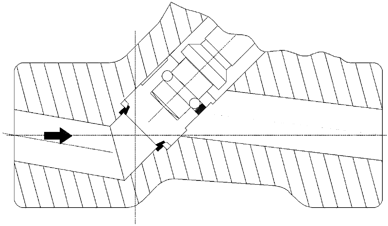
[0002] Existing anti-scouring globe valve, disc seal structure, such as figure 1 , the structure is that after the valve disc sealing surface is separated, the valve disc has not completely left the valve outlet channel, and the flow is throttled by the cooperation gap between the valve body and the valve disc, which belongs to the principle of gap sealing, thereby improving the anti-scouring performance of the valve. This structure Although the anti-scouring performance has been improved to a certain extent, according to the use of thermal power plant owners, especially for some ultra-supercritical units with ultra-high pressure and high-temperature medium at one end and atmospheric pressure at the other end, the service life is relatively short. Not ideal, seriously affecting the safety of boiler use

Method used


Image

  • High-pressure difference stop valve with U-shaped groove in outlet throttling channel
  • High-pressure difference stop valve with U-shaped groove in outlet throttling channel
  • High-pressure difference stop valve with U-shaped groove in outlet throttling channel

Examples


Embodiment Construction

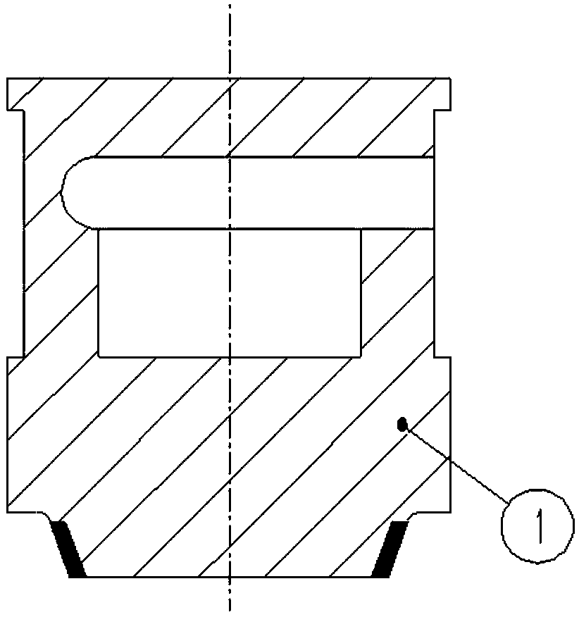
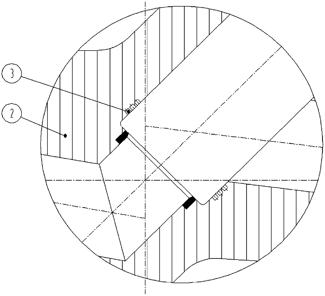
[0015] Such as figure 2 As shown, an anti-scour disc sealing structure of a high pressure differential globe valve with a concave groove in the throttling passage mainly includes a valve body 1, a valve disc 2, and a concave groove 3 at the outlet of the throttle passage of the valve body.

[0016] Such as figure 2 , 3 , As shown in 4, there are multiple labyrinth seal concave grooves at the outlet of the throttling channel of the valve body. It should be noted that because the valve disc only moves in the axial direction, the concave grooves cannot be formed by helical lines, but can only be processed into several complete concave grooves, and the number of concave grooves should be greater than or equal to 3, thus forming a straight-through labyrinth The principle of sealing, combined with the use of static sealing surface, enhances the anti-scouring performance.

[0017] Such as Figure 5 As shown, the schematic diagram of the fluid flow formed during the opening proc...


PUM


Abstract

The invention belongs to a stop valve, and particularly relates to a high-pressure difference stop valve with a U-shaped groove in an outlet throttling channel. The high-pressure difference stop valvewith the U-shaped groove in the outlet throttling channel is characterized by comprising a valve body and valve flaps, the valve flaps are arranged in the channel of the valve body, the valve flaps can be opened and closed by external control, a straight-through labyrinth seal is arranged at the outlet throttling channel in the valve body, the high-pressure difference stop valve further comprisesthe U-shaped groove in an outlet of the valve body throttling channel, and the U-shaped groove in the outlet of the valve body throttling channel is formed in the outlet throttling channel in the valve body. The high-pressure difference stop valve has the effects that through a dynamic seal principle of the U-shaped groove labyrinth seal structure, the leakage rate of the valve is effectively controlled, the fluid velocity between valve flap sealing surfaces is reduced, the overall sealing performance and the service life of the valve are improved, and the high-pressure difference stop valveis an anti-scouring stop valve quite adapted to a high-temperature and high-pressure difference environment.

Description

technical field [0001] The invention belongs to a cut-off valve, in particular to a high-pressure difference cut-off valve with a concave groove in a meter-out passage. Background technique [0002] Existing anti-scouring globe valve, disc seal structure, such as figure 1 , the structure is that after the valve disc sealing surface is separated, the valve disc has not completely left the valve outlet channel, and the flow is throttled by the cooperation gap between the valve body and the valve disc, which belongs to the principle of gap sealing, thereby improving the anti-scouring performance of the valve. This structure Although the anti-scouring performance has been improved to a certain extent, according to the use of thermal power plant owners, especially for some ultra-supercritical units with ultra-high pressure and high-temperature medium at one end and atmospheric pressure at the other end, the service life is relatively short. It is not ideal and has seriously affe...

Claims


Application Information

Patent Timeline
Patent Type & Authority Applications(China)
IPC IPC(8): F16K1/36F16K27/02
CPCF16K1/36F16K27/02
Inventor 岳阳李军业吴辉
Owner SUFA TECH IND CNNC
Learn More