A Rotating Self-Frequency Adjustment Piezoelectric Vibration Energy Harvester

A technology of energy harvester and piezoelectric vibration, applied in piezoelectric effect/electrostrictive or magnetostrictive motors, generators/motors, electrical components, etc., can solve the problem of easy-to-destroy piezoelectric material electrodes and increase structural complexity problems such as reducing the reliability of the device, increasing the working frequency bandwidth, reducing the difficulty and improving the reliability

Active Publication Date: 2021-11-19
NANJING UNIV OF POSTS & TELECOMM
View PDF6 Cites 0 Cited by
  • Summary
  • Abstract
  • Description
  • Claims
  • Application Information

AI Technical Summary

Problems solved by technology

However, this structure introduces roller bearings, which increases the complexity of the structure; at the same time, the trapezoidal beam in this structure moves back and forth in the roller bearings with the change of vehicle speed, which is easy to damage the piezoelectric material or the electrodes on the surface of the piezoelectric material, reducing the Device reliability is low

Method used


Image

  • A Rotating Self-Frequency Adjustment Piezoelectric Vibration Energy Harvester
  • A Rotating Self-Frequency Adjustment Piezoelectric Vibration Energy Harvester
  • A Rotating Self-Frequency Adjustment Piezoelectric Vibration Energy Harvester

Examples


Embodiment Construction

[0021] Embodiments of the present invention will be disclosed in the following diagrams. For the sake of clarity, many practical details will be described together in the following description. It should be understood, however, that these practical details should not be used to limit the invention. That is, in some embodiments of the invention, these practical details are not necessary. In addition, for the sake of simplifying the drawings, some well-known and commonly used structures and components will be shown in a simple schematic manner in the drawings.

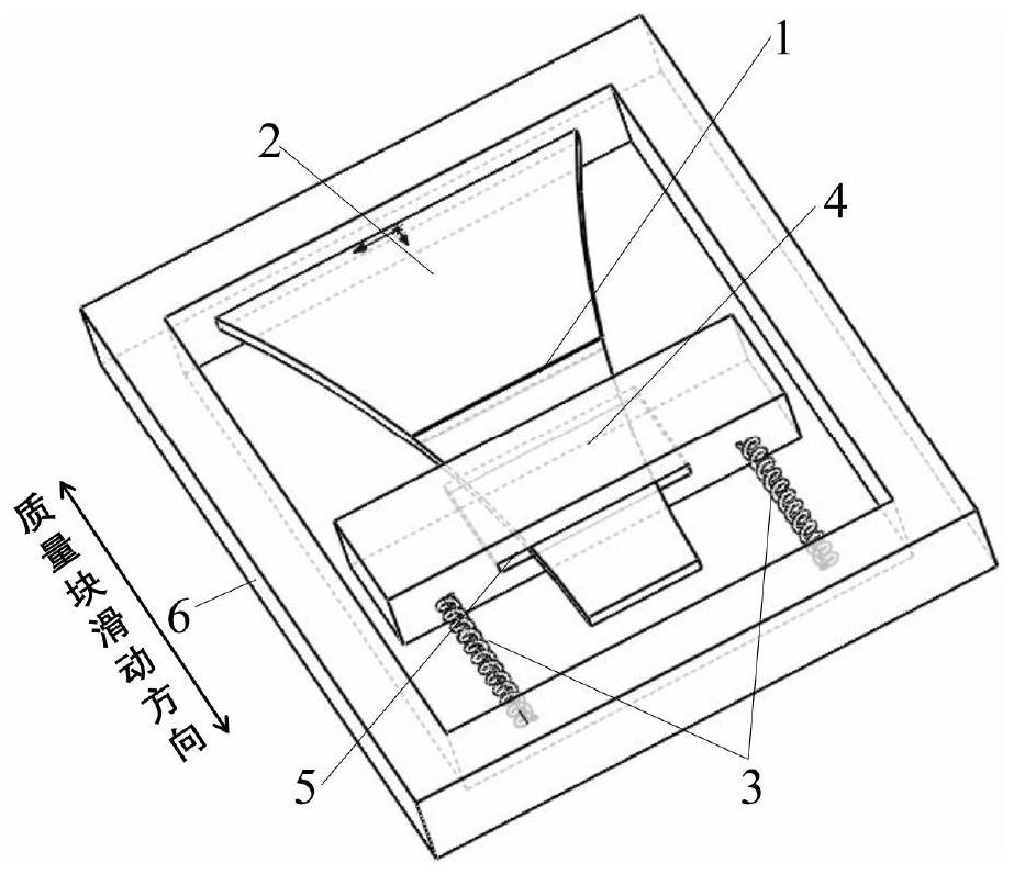
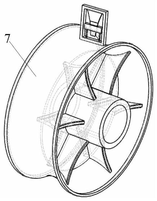
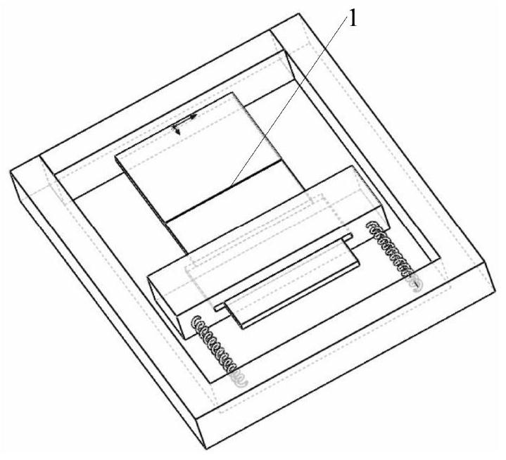
[0022] Such as Figure 1-7 As shown, the present invention is a rotary self-frequency regulating piezoelectric vibration energy harvester, comprising a main beam 1, an auxiliary beam 3, a mass block 4 and an outer frame 6, the main beam 1 is a piezoelectric beam, and the piezoelectric layer 2 and the substrate layer, one end of the main beam 1 is fixed on the outer frame 6, the other end of the main beam 1 is connected...


PUM


Abstract

The invention is a rotary self-frequency regulating piezoelectric vibration energy harvester, which includes a main beam, an auxiliary beam, a mass block and an outer frame. The main beam is a piezoelectric beam, which is composed of a piezoelectric layer and a substrate layer. One end of the main beam is fixed On the outer frame, the other end of the main beam is connected to the quality block, the sub-beam is an elastic beam, one end of the sub-beam is connected to the outer frame, the other end of the sub-beam is connected to the mass block, and a through groove is arranged in the middle of the mass block. It is connected with the main beam through the through groove, the mass block is constrained to slide in the length direction of the main beam through the through groove, and the outer frame is fixed on the rotating mechanism. When the centrifugal force of the mass block of the present invention acts on the mass block, the position of the center of mass of the mass block on the main beam changes, and the natural frequency of the vibration energy harvester is adjusted to match the rotational excitation frequency, increasing the work of the vibration energy harvester The frequency bandwidth improves the reliability of the structure and reduces the difficulty of structural design.

Description

technical field [0001] The invention relates to the technical field of energy collection, in particular to a rotary self-frequency-regulating vibration energy harvester. Background technique [0002] The rapid development and wide application of microelectronic devices and systems (such as wireless sensor network nodes, medical implant sensors, weapon equipment fault monitoring systems, etc.) require the power supply system to have the characteristics of long life, small size, and light weight. Traditional chemical energy batteries have encountered technical bottlenecks such as short life, large volume, and heavy weight during the development process, which has become one of the main obstacles restricting the development of microelectronic devices and systems. Energy harvesting that converts vibration energy in the surrounding environment into electrical energy In theory, battery technology can achieve infinitely long power supply time, and has the advantages of small size, ...

Claims


Application Information

Patent Timeline
Patent Type & Authority Patents(China)
IPC IPC(8): H02N2/18
CPCH02N2/186
Inventor 邓丽城吴蓓园方玉明
Owner NANJING UNIV OF POSTS & TELECOMM
Why Eureka
Try Eureka