
Combined casting die

A casting mold, combined technology, applied in the direction of manufacturing tools, casting molding equipment, casting molds, etc., can solve the problems of long development cycle, increased procurement costs, and inability to keep up with market needs, to reduce development costs and have a wide range of applications. Effect

Pending Publication Date: 2020-03-06
湖北伊克斯热交换系统有限公司
View PDF0 Cites 1 Cited by
  • Summary
  • Abstract
  • Description
  • Claims
  • Application Information

AI Technical Summary

Problems solved by technology

[0004] 1. The development cycle is relatively long, and the development cycle of a set of air chamber mold generally takes 45-50 days, which cannot keep up with the market demand;
[0005] 2. The cost of developing molds is relatively high, and the cost of a set of casting air chamber left and right molds is generally 50,000-80,000;
[0006] 3. Due to the needs of product transition, the production quantity of the original air chamber mold has been greatly reduced, and the production cost of the original air chamber product has increased, resulting in an increase in procurement costs

Method used


Image

  • Combined casting die
  • Combined casting die
  • Combined casting die

Examples


Embodiment 1

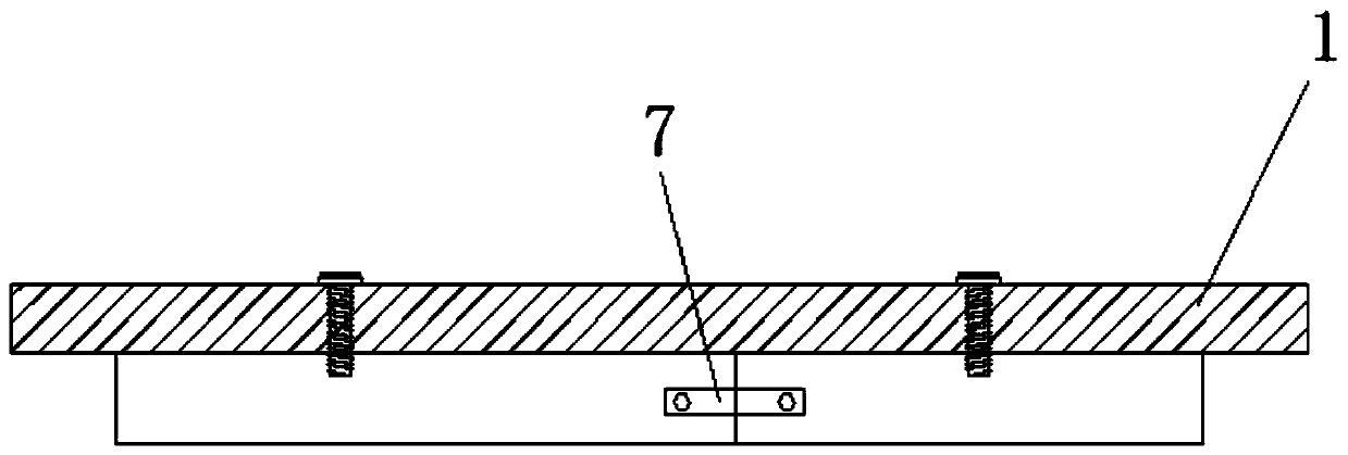
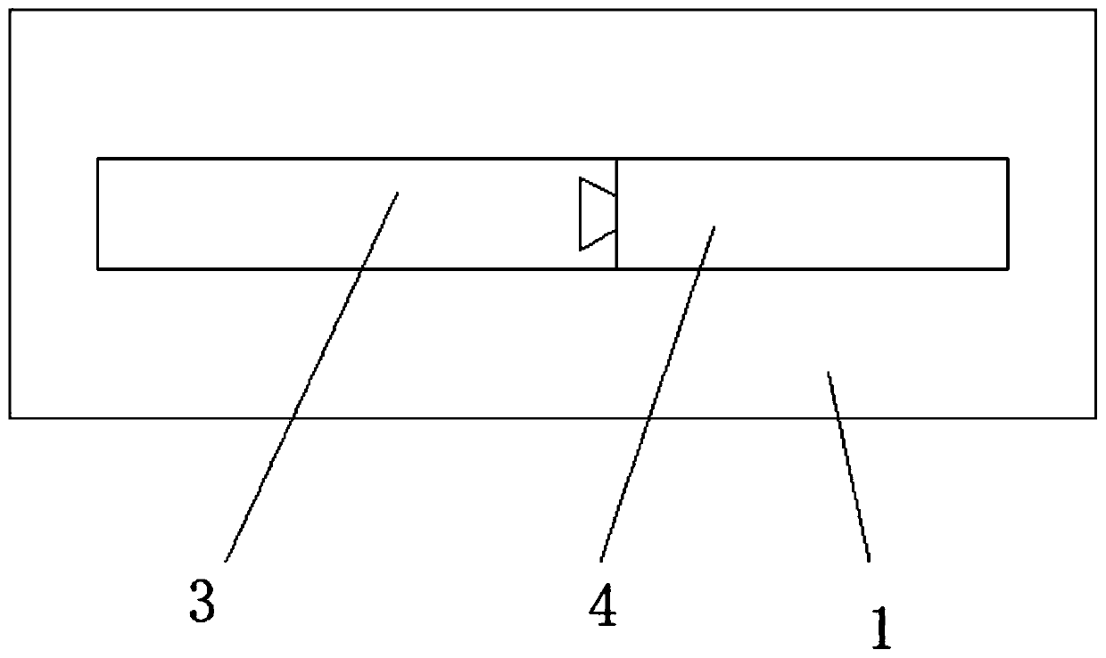
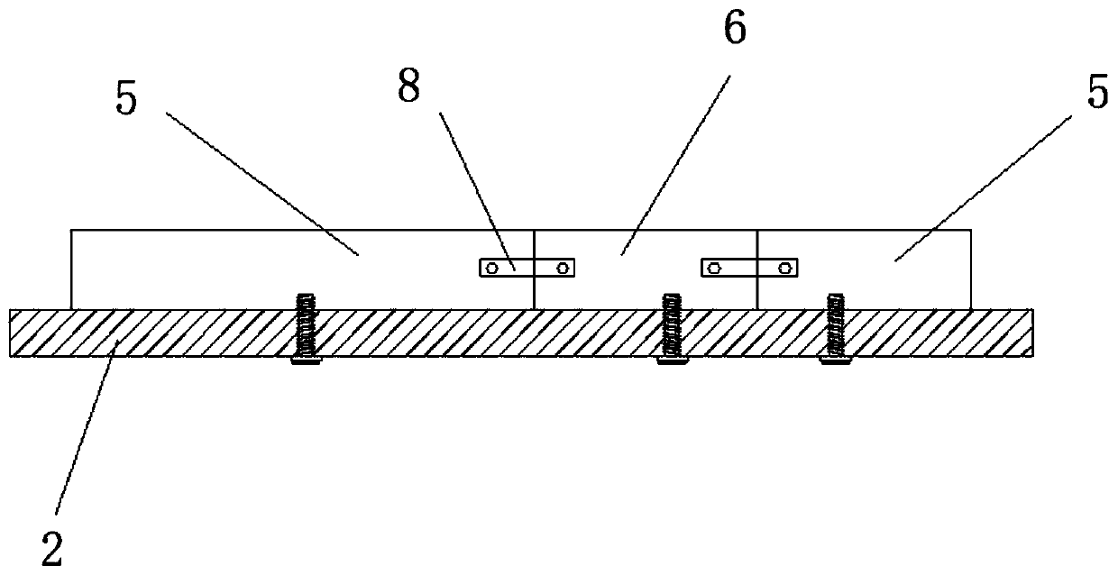
[0045] figure 1 It is a schematic structure diagram of an upper plate and punch assembly of an embodiment of the present invention. figure 2 It is a top view of an upper plate and punch assembly of an embodiment of the present invention. image 3 It is a schematic structural diagram of the lower plate and die assembly of an embodiment of the present invention. Figure 4 It is a top view of the lower plate and die assembly of an embodiment of the present invention.

[0046] Such as Figure 1-Figure 4 As shown, the combined casting mold includes: an upper plate 1, a punch assembly arranged on the upper plate 1, a lower plate 2 and a die assembly arranged on the lower plate 2, and the punch assembly When the protruding part is set in the concave part of the die assembly, a casting gap is formed between the protruding part and the concave part;

[0047] Wherein, the punch assembly includes a fixed punch 3 and a punch insert 4, at least one end of the fixed punch 3 is provided...


PUM


Abstract

The embodiment of the invention discloses a combined casting die. The combined casting die comprises an upper plate, a male die assembly, a lower plate and a female die assembly. When a convex part ofthe male die assembly is arranged in a concave part of the female die assembly, a casting gap is formed between the convex part and the concave part. The male die assembly comprises a fixed male dieand a plurality of male die inserts. At least one end of the fixed male die is provided with a slide groove. One end of each male die insert is provided with a slider. Each male die insert is slidingly arranged in the corresponding slide groove through the corresponding slider. The female die assembly comprises two fixed female dies and a plurality of female die inserts. Each fixed female die comprises an opening end and a closed end. A slide groove is formed in each opening end. The two ends of each female die insert are provided with sliders. The two ends of each female die insert are connected to the two fixed female dies through the corresponding sliders. The combined casting die is wider in application range, and the development cost of the die can be reduced.

Description

technical field [0001] The invention relates to the field of auto parts processing, in particular to a combined casting mold. Background technique [0002] The current automobile cooling system has transitioned from China V to China VI, and the cooling system has undergone relatively large adjustments, requiring an increase in the heat dissipation of the radiator and intercooler. The cooling module of the original engine with the same power cannot meet the requirements, and the product needs to be upgraded. This is mainly for the research and adjustment of the intercooler. [0003] The engine is upgraded to China VI, and its internal structure and control configuration have undergone relatively large changes, but its connection mode and position with the cooling system remain basically unchanged. In this way, the direct and relative position of the inlet and outlet pipes of the intercooler of the automobile can also be kept the same as that of the National V products. How...

Claims


Application Information

Patent Timeline
Patent Type & Authority Applications(China)
IPC IPC(8): B22C9/06B22C9/24
CPCB22C9/06B22C9/24
Inventor 刘移利魏鹏军韩宏倪拥升
Owner 湖北伊克斯热交换系统有限公司
Learn More