Telescopic umbrella

a telescopic and umbrella technology, applied in the field of telescopic umbrellas, can solve the problems of inability to extend the telescopic pipe with respect to the upright pipe after opening the umbrella canopy, the tension of the sheathed cable/bowden control is lost, and the position of the telescopic pipe with respect to the upright pipe cannot be changed withou

Inactive Publication Date: 2008-10-02
ZHEJIANG YOTRIO GRP CO LTD
View PDF8 Cites 23 Cited by
  • Summary
  • Abstract
  • Description
  • Claims
  • Application Information

AI Technical Summary

Benefits of technology

[0012]Based on the invention, it was recognized that the opening / closing movement of the umbrella canopy can be uncoupled from the telescopic mechanism of the umbrella if the control device for the sheathed cable / Bowden control is attached directly to the telescopic pipe. This way the distance between the control device and umbrella canopy always remains constant. Consequently, it is irrelevant for the opening / closing movement of the umbrella canopy how far the telescopic pipe is inserted into the upright stand pipe or how far it is pulled out of the upright stand pipe. This is a particularly advantageous way to achieve that the length of the umbrella can be changed arbitrarily even when the umbrella canopy is open, without interfering with the opening mechanism of the umbrella canopy.
[0031]In another embodiment, the engaging element can be engaged with or disengaged from the telescopic pipe via a handle by means of a screwing movement and / or with the application of radial pull / pressure with respect to the upright stand pipe, against the force of a spring, if applicable. For example, it is possible that the engaging element / the pin are connected to a nut with the approximate size of the palm of a hand, e.g., made of plastic. This user-friendly nut extends to an exterior thread with a smaller diameter which engages with an interior thread within the borehole in the upright stand pipe. The engaging element or the pin is connected to the exterior thread in the direction of the inside of the pipe. As a result, the engaging element can be engaged with the telescopic pipe by means of unscrewing and screwing on of the user-friendly nut. In addition, it is possible that a spring is provided in addition to the thread, where an elastic force needs to be overcome after unscrewing the nut to be able to pull the engaging element out of the telescopic pipe. Accordingly, the nut not only needs to be unscrewed, but the user is required to pull on the nut to unlock the telescopic pipe. This further development achieves a particularly safe use of the umbrella according to the invention.

Problems solved by technology

Firstly, the position of the telescopic pipe with respect to the upright pipe after opening the umbrella canopy can no longer be changed without first closing the umbrella canopy again.
If you wish to lower the position of the telescopic pipe, i.e., by inserting it into the upright stand pipe, the umbrella canopy automatically folds because the tension of the sheathed cable / Bowden control is lost.
In the known telescopic umbrella, the extension of the telescopic pipe with respect to the upright stand pipe is not possible at all when the umbrella canopy is open, because the tension of the sheathed cable / Bowden control resists the extension movement.
In addition, the fact that the sheathed cable / Bowden control can gradually be worn through as a result of the sharp-edged transition between the telescopic pipe and the upright stand pipe by fraying and ultimately tearing is problematic with respect to the known telescopic umbrella.
Another disadvantage is that the sheathed cable / Bowden control in the known telescopic umbrella can interfere with the locking mechanism for the telescopic pipe, resulting in identical adverse consequences in terms of the durability of the sheathed cable / Bowden control.
Finally, another disadvantage is that the control device for the sheathed cable / Bowden control arranged in the upright stand pipe hinders the movement of the telescopic pipe within the upright stand pipe; as a result, it may be possible that the telescopic pipe can only be inserted into the upright stand pipe at a fraction of its length.
Consequently, the variability of the length of the known telescopic umbrella is limited, requiring more storage space when if the telescopic pipe is inserted as far as possible.
This option is not available in the umbrellas known from prior art, because the telescopic mechanism collides with the opening movement of the umbrella canopy.

Method used


Image

  • Telescopic umbrella
  • Telescopic umbrella
  • Telescopic umbrella

Examples


Embodiment Construction

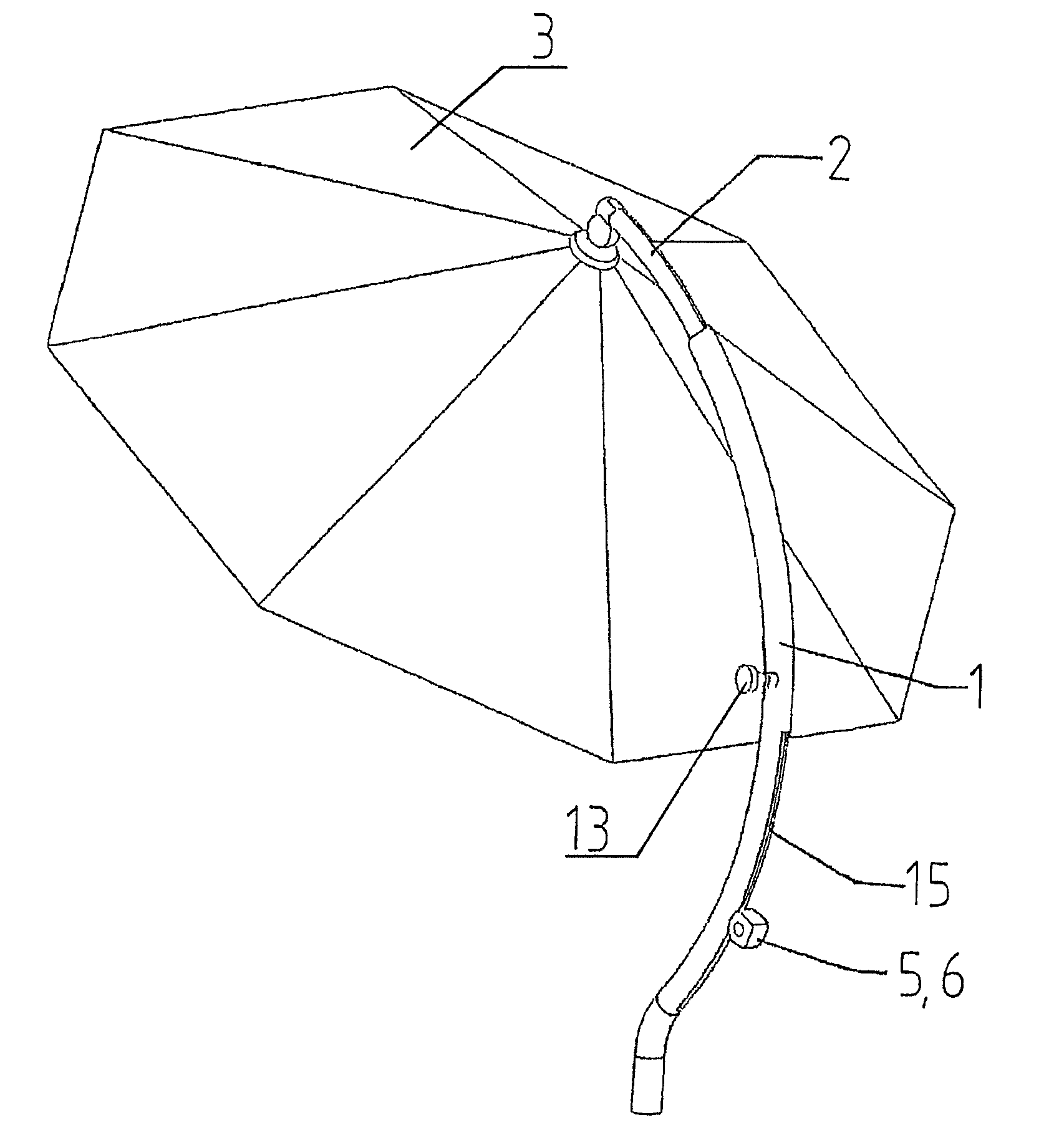
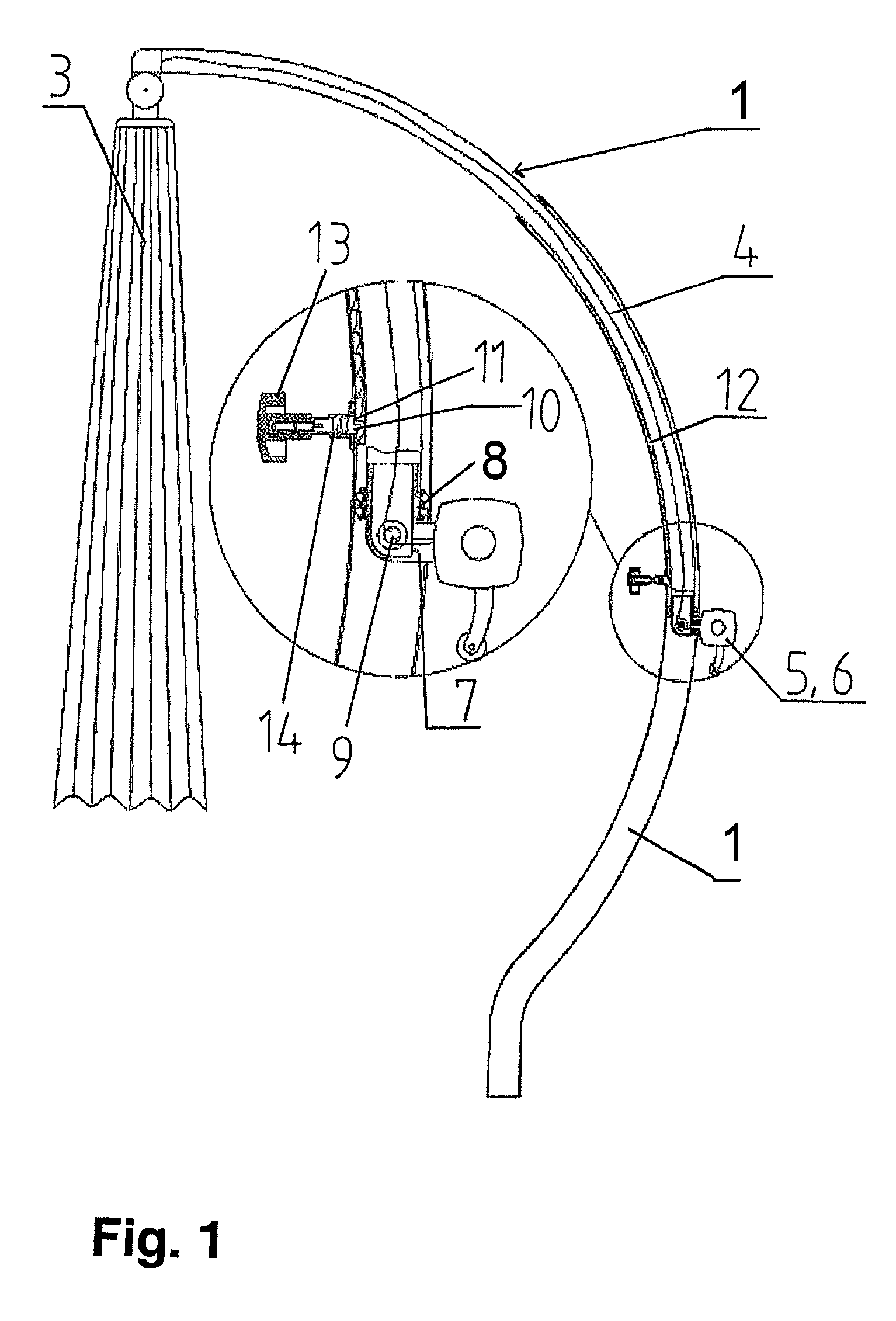
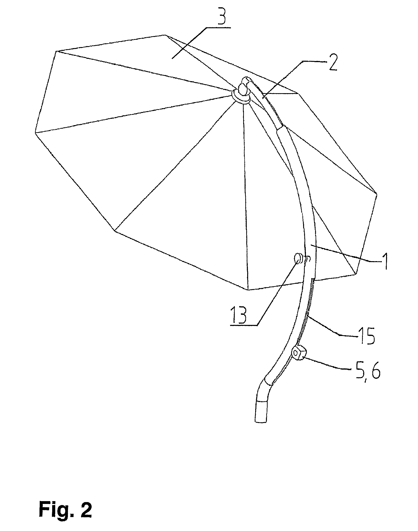
[0037]FIG. 1 shows a partially cut lateral view of a preferred embodiment of the telescopic umbrella according to the invention. The umbrella comprises a lower upright stand pipe 1 and a telescopic pipe 2 which can be moved and locked in the upright stand pipe. An umbrella canopy 3 is joined to the telescopic pipe 2. In this embodiment, both the upright stand pipe 1 as well as the telescopic pipe 2 comprise a curvature, making it possible to suspend the umbrella canopy 3 from the upper end of the telescopic pipe 2. This provides the greatest possible distance between the upright stand pipe or the supporting base from the area shaded by the umbrella canopy 3.

[0038]The umbrella canopy 3 can be opened and closed by means of a sheathed cable / Bowden control 4. For this purpose, the sheathed cable / Bowden control 4 is connected to a control device and can be operated with it. In the embodiment shown, the control device 5 is designed as a crank shaft 6.

[0039]Based on the invention, the cont...


PUM


Abstract

A telescopic umbrella, such as a sunshade, that includes a lower upright stand pipe and a telescopic pipe arranged in a displaceable and arrestable manner therein. The telescopic umbrella also includes a canopy articulated on the telescopic pipe, it being possible for the canopy to be opened and closed by means of a sheathed cable or Bowden control running within the telescopic pipe and controlled by a control device. The control device is attached to the telescopic pipe so that the opening / closing movement of the umbrella canopy is uncoupled from the telescopic mechanism of the umbrella.

Description

CROSS-REFERENCE TO RELATED APPLICATIONS[0001]The present application is a Continuation of International Application No. PCT / DE2006 / 000915, filed May 26, 2006, and which designates the U.S. The disclosure of the referenced application is incorporated herein by reference.FIELD OF THE INVENTION[0002]The invention relates to a telescopic umbrella, in particular a sunshade with a lower upright stand pipe and a moveable and lockable telescopic pipe arranged in it with an umbrella canopy attached to the telescopic pipe, where the umbrella canopy can be opened and closed by means of a sheathed cable or Bowden control arranged within the pipe and with a control device for the sheathed cable or Bowden control.BACKGROUND OF THE INVENTION[0003]Telescopic umbrellas of the type in hand are known from prior practice. The control device for the sheathed cable or Bowden control of these umbrellas generally consists of a crank handle provided in the lower region of upright stand pipe or on the suppor...

Claims


Application Information

Patent Timeline
Patent Type & Authority Applications(United States)
IPC IPC(8): A45B19/04
CPCA45B23/00A45B25/14A45B2023/0012A45B2023/0037A45B2023/0062A45B2023/0081A45B2025/146
Inventor HUALI, GUOPENG, ZHAHUHUA, ZHOU
Owner ZHEJIANG YOTRIO GRP CO LTD
Why Eureka
Try Eureka