Telepole, and related methods

a technology of telepole and telescoping rod, which is applied in the field of telescoping rods, can solve the problems of inability to perform adequately in use, heavy tools, likewise heavy or bend, etc., and achieve the effects of preserving the buoyancy of the inner tube, facilitating grasping/gripping, and adding strength

Active Publication Date: 2017-09-19
RESH INC
View PDF27 Cites 26 Cited by
  • Summary
  • Abstract
  • Description
  • Claims
  • Application Information

AI Technical Summary

Benefits of technology

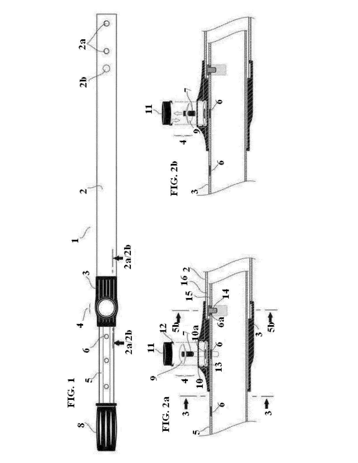
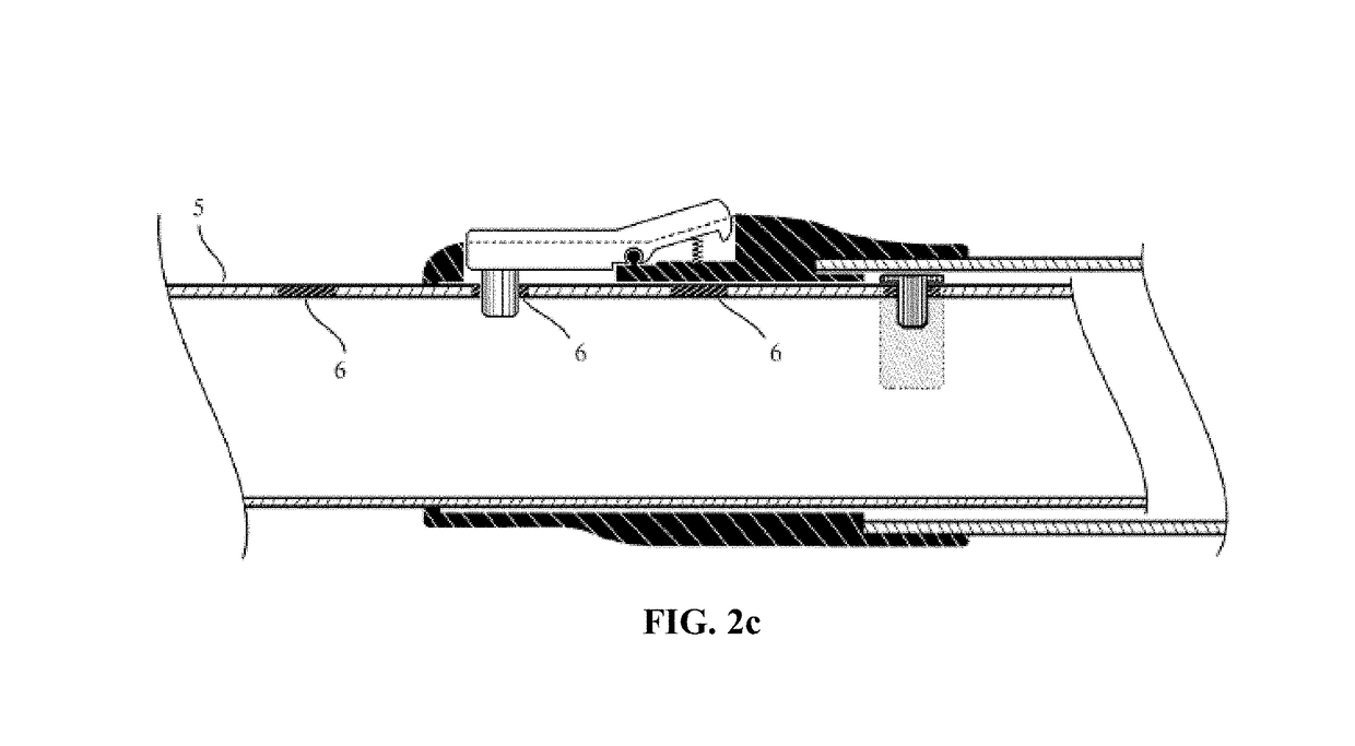
[0026]It is, therefore, an object of my invention to provide an improved telepole device having attachment means for attaching swimming pool cleaning tools. The improved telepole device preferably includes an inner tube which freely slides within an outer tube, and a locking device to temporarily secure said inner tube in a desired position within the outer tube. In a preferred embodiment, both the inner and outer tubes are fabricated from aluminum or a similar material that is both lightweight and durable, and most of the inner tube's length can slide into and extend out from one end of the outer tube. A preferred lightweight design may be at least partially hollow along the length of the tube(s), and durability may be provided by inner / reinforcement wall(s) that extend across the hollow portion(s) of one or both of the tubes. Preferably, one end of the inner tube has a grip mounted thereon which makes that end easy to grasp / grip and also prevents the inner tube from sliding entirely within the outer tube. On the end of the outer tube through which the inner tube slides / extends is a collar element attached thereto and comprised of a locking device having a detent mechanism for “locking” the inner tube in place within the outer tube. Additionally, the inner tube preferably has a distinct profile that matches the opening of the collar element through which it extends. Preferably, the collar's opening and the profile of the inner tube have one or more sides that, due to their relative position with respect to each other, can prevent the inner tube from rotating within the collar. Further, the inner tube preferably has a series of holes along its length which are positioned to receive a pin element of the detent mechanism. The pin element is preferably attached to a spring element and held in place by a housing which is formed into the collar. In its normal “resting” position, the spring pushes the pin towards the inner tube such that, when the pin is aligned with one of the holes in the inner tube, the pin sits in the hole and “locks” the inner tube in position so that it cannot slide / rotate within the outer tube or collar. Also preferably, within an upper portion of the housing above the pin is a button that, when depressed, forces the spring to reverse itself from its normal “resting” position and consequently lifts / releases the pin from its normal position in the housing so that the inner tube may be moved to a new position. Further, the end of the outer tube opposite the collar preferably has attachment holes configured to receive attachable and detachable swimming pool cleaning tools, and an additional set of holes that allow water to drain from the outer tube while a tool is attached.
[0027]A further object of my invention is to provide a telepole for cleaning swimming pools, with a detent mechanism as described above, and characteristics that prevent water from entering the inner tube during use so as to preserve the inner tube's buoyancy. In a preferred embodiment, a barrier is formed or otherwise provided inside the inner tube along its length and adjacent to the length-selection holes, to prevent water that may flow through those holes from entering the bulk of the inside portion of the inner tube. In addition, the telepole's buoyancy preferably is further maintained by a plug which is preferably mounted into or otherwise on the end of the inner tube that is opposite the gripping portion. The plug prevents water from entering the inner tube through its end. The end of the outer tube opposite the collar preferably has holes configured to receive attachable and detachable swimming pool cleaning tools.
[0028]Another object of my invention is to provide a telepole for cleaning swimming pools, with a compression device to “lock” / temporarily secure the inner tube within the outer tube at a desired position along the inner tube's length. The compression device and the inner tube preferably have corresponding detent-like contact surfaces that engage and disengage each other when the compression device is tightened and loosened, respectively, and enable a user to change the length of the telepole as needed.
[0029]Still another object of my invention is to provide a stronger telepole for cleaning swimming pools, including an inner tube that slides within an outer tube and can be “locked” / secured in various places along the length of the inner tube. The inner tube has one or more additional inner / reinforcement walls along its length to add strength and to help keep the inner tube true and round.
[0030]Yet another object of my invention is to create a telepole for cleaning swimming pools, including an outer tube having a collar on one end, the collar having a central opening through which an inner tube extends. The collar's opening and the profile of the inner tube have one or more sides keyed to each other such that, due to their shapes, the inner tube cannot rotate within the collar. The collar preferably is configured to include a compression device to lock the inner tube at any given area along its length.
[0031]Still another object of my invention is to provide a telepole assembly and related methods for cleaning swimming pools, including an inner tube and an outer tube, and further including a lever-action compression device that is easy on a user's hands. In one of many potential embodiments, the lever is installed in a housing formed within a collar that is mounted on the end of an outer pole. The housing is configured to prevent the lever's edges or corners from protruding in such a way that they might be accidentally bumped by a user's hands or some other object that may disengage the lever. The inner tube preferably has a distinct profile that matches and / or is keyed to the opening of the collar, the compression device, or both, through which it extends. Among various embodiments, the collar's opening, the compression device, or both, and the profile of the inner tube can have one or more flat sides that, due to their shapes, prevent the inner tube from rotating within the collar. The inner tube preferably has a plug in its end furthest from the grip, said plug preserving buoyancy by preventing water from entering the inner tube.

Problems solved by technology

Some of the problems with prior art extendable handles, however, are associated with the failure of the handles to perform adequately during use.
Sometimes manufacturers use harder woods to reduce such breakage; however, hard woods tend to weigh more than softer woods and consequently, make the tools heavier.
Handles made of metal tubes are often used, but these may likewise be heavy or bend when under pressure.
It is also common for handles on shovels, rakes, brooms, etc. to be made from synthetic materials such as plastic or fiberglass; such handles likewise may be heavy, lack strength or fail for other reasons.
However, handles of this length may easily sag in the middle between the user and the tool, and manufacturers have attempted to reduce sagging by increasing the diameter and thickening the walls of the tubular sections.
In doing so, they use a greater amount of material (typically aluminum within the concrete industry) and, consequently, make the handles heavier and more difficult to work with.
However, when the user sufficiently further rotates the inner tube with respect to the outer tube, the inner tube's cam element becomes misaligned with the profile of the inner walls of the outer / lower tube, and the cam element applies a pressure against the inner walls of the outer tube and “locks” the inner tube in place within the outer tube.
Repeated use results in wear and tear on the cam and / or the inner walls of the outer tube, causing the contact surfaces of the cam and inner walls to become rough and / or out of round.
As a result, a cam may lose its ability to become misaligned with the inner walls of the tube and as a consequence the inner and outer tubes cannot be “locked” in place with respect to each other.
In this situation, the cam may also spontaneously align itself with the inner walls of the tube, thus permitting the tubes to readily slide past one another and causing the telepole to collapse / slip when pressure is applied to it during cleaning.
The tendency of the cam to spontaneously align with the inner walls may also result in tool failure and even poses the risk of the user falling into the pool if the telepole suddenly collapses while the user is applying pressure to it.
Further, prior art telepoles are prone to bending / becoming deformed during use due to the amount of pressure / weight applied to them by a user.
When this happens, the telepole's internal locking devices tend to jam in the areas where the tubes are out of round and / or not straight, resulting in complete failure of the telescopic feature of the pole.
In other words, and among other things, poles in this condition may not be extendable or adjustable in length.
Additionally, prior art external locking devices are subject to wear and tear in prior art telepole devices.
Over time, the contacting surfaces can wear and / or become smooth and have less friction, which greatly reduces the ability of the compression ring to hold the inner tube in place.
The inner tube may also undesirably rotate when the telepole is in use, thus reducing the user's ability to maneuver the attached cleaning tools as desired.
Furthermore, telepoles having only an external locking device have the additional problem of water filling the inner tube during use since there is no cam to plug the end of the inner tube.
This can make the telepole very heavy and less maneuverable (as mentioned above, some water inside the tube(s), such as in the lower tube, can be helpful in using the tool, but too much water can be a substantial problem or inconvenience in using the tool).
Even further, new prior art telepoles having new compression rings have been known to undesirably permit inner tube rotating and / or sliding within the outer tube.
Attempts to remedy these known issues / problems have led to even more problems.
One such attempt increases the tightening force of the compression ring, but it can make the compression ring very difficult to loosen and painful to the user's hands to twist the compression ring either to tighten or loosen it.
The issues described above are common among prior art telepoles used to clean swimming pools and have led to the creation of telepoles with both internal and external locking devices, wherein either device may serve as a backup for the other.
Over time, however, the areas of contact between the tubes become rough and develop friction, and the inner tube may become jammed within the outer tube.
Further, “telepoles” or extendable handles used in other applications are not necessarily suitable for use in swimming pools.
Furthermore, telepoles such as those used for window washing or painting would be especially impractical as the locking devices would be almost constantly under water, hindering the ease and ready adjustment of the telepole's length needed to clean a swimming pool.
Also, the locking devices of telepoles used in other applications are unsuitable for swimming pool cleaning applications.
For instance, external locking devices, such as those found on telepoles used for window washing, painting, or marine applications, tend to make pool cleaning difficult as they can easily catch on the edge of a pool or other objects when the telepole is being used, among other things.
For example, the Mr. Long Arm Pole (shown in U.S. Pat. No. 5,220,707) has an external locking device with a button that activates a detent mechanism to engage and release the inner tube of the telepole, but is not suitable in swimming pool applications for a number of reasons.
Further, the Mr. Long Arm pole is sealed at both ends by a grip on the outer tube end and a threaded adapter on the inner tube end, and therefore is unable to accommodate the commonly-used V-clips of most swimming pool cleaning tools.
These openings in the inner tube would allow water to enter the pole when it is placed in a pool, etc. and make the telepole awkward and cumbersome to maneuver and control during use.
Additionally, since the grip is mounted on the end of the outer pole, the detent mechanism would almost always be underwater during use, and adjusting the pole's length would inconveniently require a user to withdraw some or all of the pole from the pool.
Therefore, bulky and / or angular levers that are commonly used on telepoles for other applications may obstruct a user's hand from easily passing back and forth over the lever and thus reduce a user's ability to effectively clean a swimming pool.
Furthermore, bumping a lever may cause pain or even injury to a user, especially if his or her hands have been wet for some time or exposed to pool chemicals.
Even further, bumping the lever with one's hands, an object, or even against the pool deck may cause the lever to release unintentionally.
Still other problems occur with prior art as the inner tube may easily be overextended, especially among telepoles used for cleaning swimming pools.
As a result, the outer tube, along with the attached cleaning tool, can sink to the bottom of a pool and be difficult to retrieve.
Reassembling the telepole can be difficult and especially inconvenient if the inner tube has a cam locking device mounted on it since reassembly of the telepole requires that the cam's shoe, the inside tube and outside tube all must be aligned with each other for them to slide back together.
Additional problems arise with grips that fail to remain tightly attached to the end of the inside tube.
While grips are generally designed to fit very tightly, they still can be knocked off the end of the inside tube if that tube slides too far or too quickly into the outside tube.

Method used


Image

  • Telepole, and related methods
  • Telepole, and related methods
  • Telepole, and related methods

Examples


Embodiment Construction

[0082]Embodiments of the present invention will now be described with references to the accompanying figures, wherein like reference numerals refer to like elements throughout. The terminology used in the description presented herein is not intended to be interpreted in any limited or restrictive manner, simply because it is being utilized in conjunction with a detailed description of certain embodiments of the invention. Furthermore, various embodiments of the invention (whether or not specifically described herein) may include novel features, no single one of which is solely responsible for its desirable attributes or which is essential to practicing the invention herein described.

[0083]Although the examples of the many various methods of the invention are described herein with steps occurring in a certain order, the specific order of the steps, or any continuation or interruption between steps, is not necessarily intended to be required for any given method of practicing the inve...


PUM


Abstract

A telepole for swimming pool cleaning is disclosed as including an inner tube and a locking device to temporarily secure the inner tube in a desired position within an outer tube. A preferred lightweight design may be at least partially hollow, and durability may be provided by inner/reinforcement wall(s) in one or both of the tubes. A collar element is disclosed as “locking” the inner tube in place within the outer tube. The collar's opening and the profile of the inner tube are disclosed in a relationship that prevents the inner tube from rotating within the collar. The inner tube is disclosed as having a series of holes along its length to receive a pin element of a detent mechanism. The end of the outer tube opposite the collar is disclosed as having multiple sets of attachment holes to receive attachable and detachable swimming pool cleaning tools.

Description

CROSS-REFERENCE TO RELATED APPLICATIONS[0001]This application claims priority to U.S. Provisional Application Ser. No. 61 / 538,074, filed Sep. 22, 2011, the disclosure of which is incorporated herein by reference in its entirety.FIELD OF THE INVENTION[0002]This invention relates to devices for cleaning swimming pools and similar things, and more specifically is directed to apparatus and methods involving an improved telescopic pole useful for (among other things) attachment to swimming pool cleaning tools.BACKGROUND OF THE INVENTION[0003]Many prior art tools are made with extendable handles which serve at least three key functions, among others: they provide a means for a user to grip the tool, they increase extension and reach, and they create leverage. For example, a typical shovel has a pan-shaped head for digging and / or moving dirt. An extendable handle attached to the shovel head allows a user to work in a standing position and keep their hands at a reasonable distance from the ...

Claims


Application Information

Patent Timeline
Patent Type & Authority Patents(United States)
IPC IPC(8): B25G1/04B25G3/18
CPCB25G1/04B25G3/18
Inventor RESH, ERIC
Owner RESH INC
Why Eureka
Try Eureka