
Rotor positioning method and positioning device and control system of brushless DC motor

A technology of brush DC motor and positioning method, which is applied in the direction of control system, electronic commutation motor control, starting device, etc., to achieve the effect of reducing time, solving the problem of positioning error, and solving abnormal noise and jitter

Active Publication Date: 2020-03-06
JIANGSU MIDEA CLEANING APPLIANCES +1
View PDF6 Cites 1 Cited by
  • Summary
  • Abstract
  • Description
  • Claims
  • Application Information

AI Technical Summary

Problems solved by technology

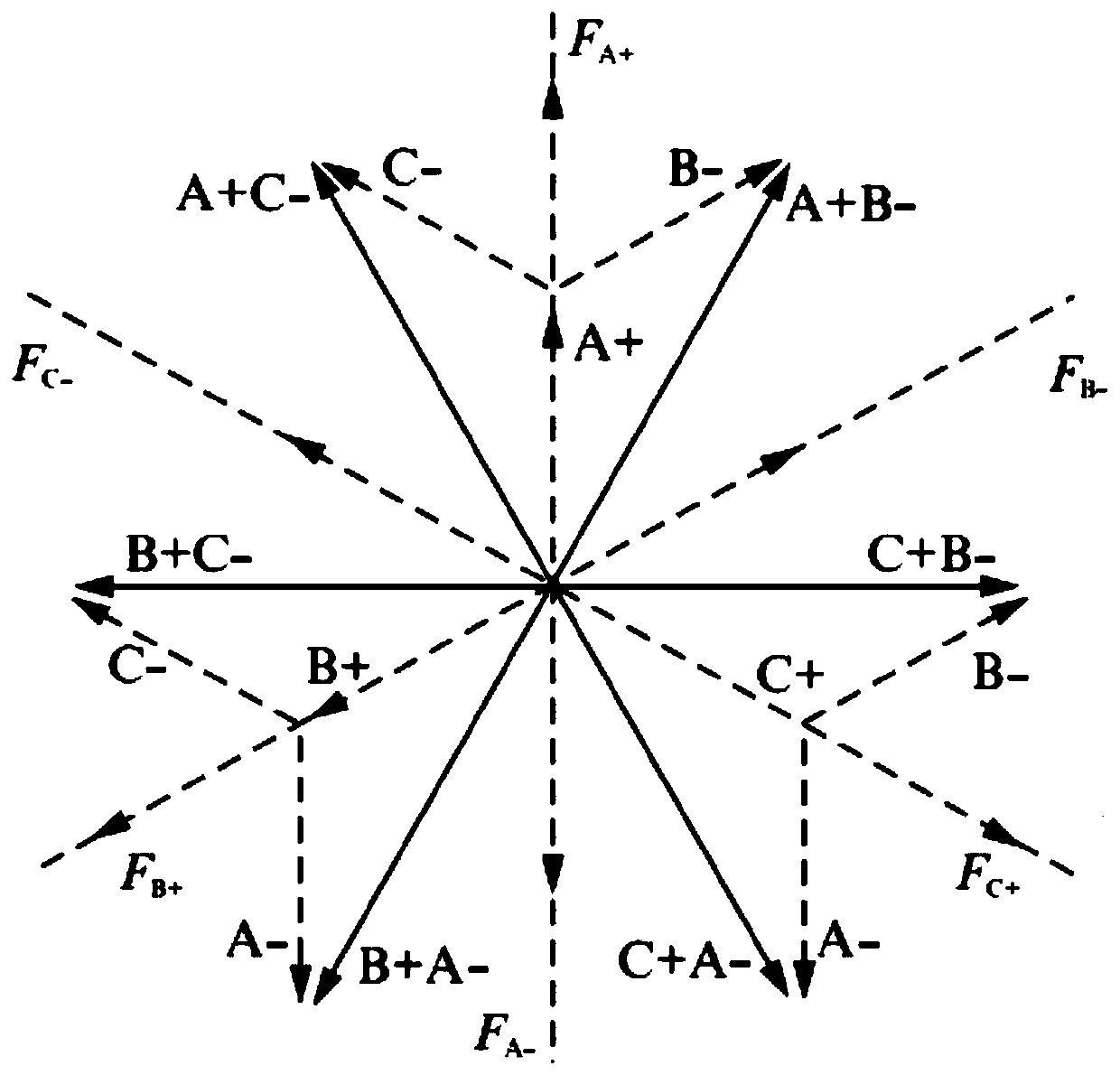
For this reason, the first purpose of the present invention is to propose a rotor positioning method for a brushless DC motor, which can not only greatly reduce the time for starting and positioning the motor, but also ensure that the motor will not reverse when starting, and solve the problem of abnormal noise and vibration during positioning. Jitter can also solve the positioning error problem caused by the mismatch between the current waveform and the rotor position during pulse positioning, simplifies the pulse positioning rotor position identification method, and can realize full 360° no blind zone positioning

Method used


Image

  • Rotor positioning method and positioning device and control system of brushless DC motor
  • Rotor positioning method and positioning device and control system of brushless DC motor
  • Rotor positioning method and positioning device and control system of brushless DC motor

Examples


Embodiment Construction

[0044] Embodiments of the present invention are described in detail below, examples of which are shown in the drawings, wherein the same or similar reference numerals designate the same or similar elements or elements having the same or similar functions throughout. The embodiments described below by referring to the figures are exemplary and are intended to explain the present invention and should not be construed as limiting the present invention.

[0045] A rotor positioning method for a brushless DC motor, a non-transitory computer-readable storage medium, a rotor positioning device for a brushless DC motor, and a control system for a brushless DC motor according to embodiments of the present invention will be described below with reference to the accompanying drawings.

[0046] Usually, the stator core of the brushless DC motor is wound with a current-carrying coil. When the current-carrying coil is passed into the current, a certain magnetic flux will be generated in the ...


PUM


Abstract

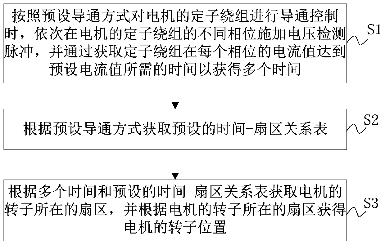
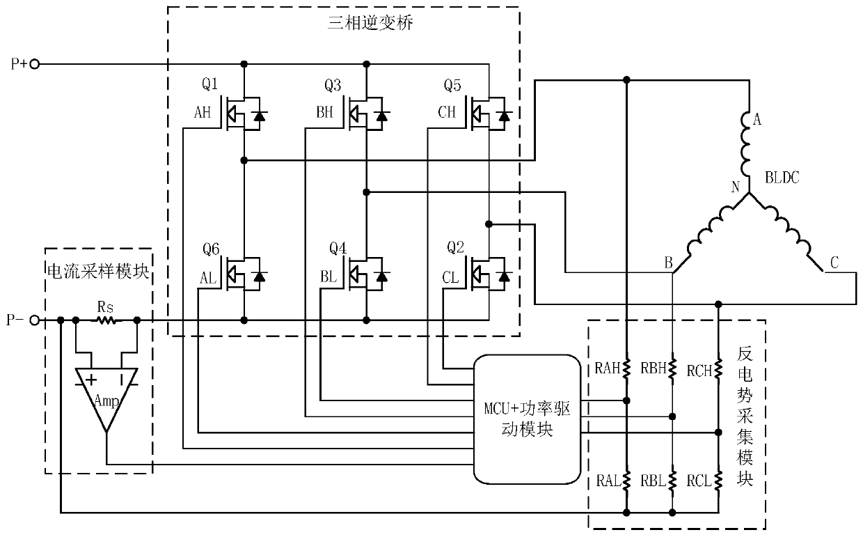
The invention discloses a rotor positioning method and positioning device and a control system of a brushless direct current motor. The positioning method comprises the following steps: when conduction control is carried out on the stator winding of the motor according to a preset conduction mode, voltage detection pulses are sequentially applied to different phases of the stator winding of the motor, and a plurality of times are obtained by obtaining the time required for the current value of the stator winding at each phase to reach a preset current value; obtaining a preset time-sector relation table according to the preset conduction mode; and obtaining a sector where the rotor of the motor is located according to a plurality of times and the preset time-sector relation table and obtaining the rotor position of the motor according to the sector where the rotor of the motor is located. Therefore, the rotor position of the motor can be quickly and accurately obtained, the problems ofabnormal sound, shaking and positioning errors are avoided and the method is simple and can realize non-blind area positioning.

Description

technical field [0001] The invention relates to the technical field of motor control, in particular to a rotor positioning method of a brushless direct current motor, a rotor positioning device of a brushless direct current motor and a control system of a brushless direct current motor. Background technique [0002] At present, in the field of brushless DC motor sensorless drive control technology, there are mainly two rotor positioning technologies when the motor is stationary and close to zero speed: forced pre-positioning method and pulse positioning method. [0003] Among them, the forced pre-positioning method does not consider the current position of the motor rotor, but energizes the fixed phase of the motor stator winding to make the motor rotor rotate to a predetermined position. However, this method has the following disadvantages: 1) The positioning time is long, which is not suitable for the occasion where the motor is required to start quickly; 2) In order to re...

Claims


Application Information

Patent Timeline
Patent Type & Authority Applications(China)
IPC IPC(8): H02P6/185H02P6/22
CPCH02P6/185H02P6/22
Inventor 万德康王浩东吴偏偏
Owner JIANGSU MIDEA CLEANING APPLIANCES
Learn More