A valve plate, valve, micro piezoelectric pump and fluid conveying device

A technology for piezoelectric pumps and valves, which is applied to parts, pumps, and pump components of pumping devices for elastic fluids, and can solve problems such as deformation of valves, increase stiffness, increase rigidity, and prevent deformation Effect

Active Publication Date: 2020-05-19
常州威图流体科技有限公司
View PDF7 Cites 0 Cited by
  • Summary
  • Abstract
  • Description
  • Claims
  • Application Information

AI Technical Summary

Problems solved by technology

[0006] In order to solve the technical problem that the valve plate is easily deformed when it is opened and closed in the prior art, the present invention proposes a valve plate, a valve, a micro piezoelectric pump and a fluid delivery device, which solve the above technical problems

Method used


Image

  • A valve plate, valve, micro piezoelectric pump and fluid conveying device
  • A valve plate, valve, micro piezoelectric pump and fluid conveying device
  • A valve plate, valve, micro piezoelectric pump and fluid conveying device

Examples


Embodiment 1

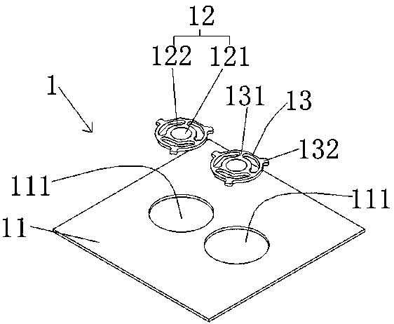
[0051] Such as Figure 1-14 As shown, the present embodiment provides a valve plate 1, including a valve plate body 11 and a valve body 12, two mounting holes 111 are opened on the valve plate body 11, two valve bodies 12 are formed, and the two valve bodies 12 are The centers are arranged symmetrically in the two installation holes 111 .

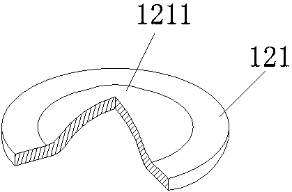
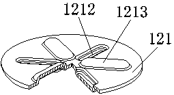
[0052] Specifically, the installation holes 111 are through holes, and the two installation holes 111 are symmetrically arranged on the valve body 11 . Preferably, the mounting hole 111 is circular. The structures of the two valve bodies 12 are the same. Taking one valve body 12 as an example, the valve body 12 can be divided into a holding area 121 and a contact area 122. The contact area 122 is annular. There is at least one protrusion on the area 121, and the back surface corresponding to the protrusion is concave. Such as figure 2 As shown, a first protrusion 1211 is provided on the holding area 121, and the first protrusion 1211 e...

Embodiment 2

[0073] Such as Figure 15 As shown, the present embodiment is basically the same as the first embodiment, the only difference being that the pressure plate 2 of the present embodiment is provided with a pre-tightening member 23 to provide pre-tightening force for the valve body 12 . Specifically, the pretensioning member 23 is annular, and the pretensioning member 23 is arranged on the end surface of the pressure plate 2 close to the valve body 12 and arranged around the port of the small flow hole 22 . There are two pre-tightening members 23, which are arranged near the two small flow holes 22, and provide pre-tightening force for the two valve bodies 12 respectively.

Embodiment 3

[0075] Such as Figure 16 As shown, this embodiment is basically the same as Embodiment 1, the only difference is that at least two micro piezoelectric pumps are included in the fluid delivery device, and at least two micro piezoelectric pumps are arranged in parallel. Correspondingly, the two fluid pipes 63 on the mounting base 6 are bifurcated, respectively communicating with two micro piezoelectric pumps.


PUM


Abstract

The invention relates to the field of fluid control, in particular to a valve plate, a valve, a micro piezoelectric pump and a fluid delivery device. A valve plate, comprising: a valve plate body, two installation holes are opened on the valve plate body; there are two valve bodies, and the two valve bodies are hung on two In the installation hole, the valve body can reciprocate relative to the installation hole where it is located, the valve body includes a contact area and a holding area, the holding area is located on the inner periphery of the contact area, and the holding area The region has at least one protrusion, and the back surface corresponding to the protrusion is concave. The quality of the valve plate is unchanged, the rigidity is increased, and when it is opened and closed, it will not be deformed by the impact of the fluid, which solves the technical problem that the valve plate is easily deformed when it is opened and closed in the prior art.

Description

technical field [0001] The invention relates to the field of fluid control, in particular to a valve plate, a valve, a micro piezoelectric pump and a fluid delivery device. Background technique [0002] With the increasing miniaturization of piezoelectric pumps, piezoelectric pumps have frequently appeared in microfluidic control and delivery instruments such as drug controlled release and chemical analysis. However, the problem brought about by miniaturization is that the valve plate that is too thin and has a small mass will deform when it is opened and closed, mainly manifested as wrinkles. After the valve plate is deformed, the opening of the inlet valve plate will be insufficient when the flow is in, and the inlet valve plate cannot be completely closed when the flow is out, and the output performance of the piezoelectric pump will be greatly affected. [0003] For example, the Chinese application with the publication number CN207064211U discloses a miniature water jet...

Claims


Application Information

Patent Timeline
Patent Type & Authority Patents(China)
IPC IPC(8): F04B53/10F04B43/04
CPCF04B43/046F04B53/102F04B53/109
Inventor 吴垠张磊周京京舒培钟德坤
Owner 常州威图流体科技有限公司
Why Eureka
Try Eureka