
Device for measuring temperature in equipment cavity

A technology for measuring devices and internal temperature, which is applied to measuring devices, parts of thermometers, thermometers, etc., can solve problems such as errors, inaccurate measurement results, and difficulty in obtaining actual temperature directly and accurately by contact measurement methods, and achieve increased Measuring range, temperature accuracy, and the effect of expanding the application range

Inactive Publication Date: 2020-03-10
NINGBO FOTILE KITCHEN WARE CO LTD
View PDF8 Cites 2 Cited by
  • Summary
  • Abstract
  • Description
  • Claims
  • Application Information

AI Technical Summary

Problems solved by technology

[0004] When the contact measurement method is used to measure the temperature in the corresponding cavity when the equipment is working, since the entire cavity is in a sealed environment when the equipment is working, it is difficult for the contact measurement method to directly and accurately obtain the actual temperature in the equipment cavity, and Due to the high temperature in the cavity, the range of the existing contact measuring device is also difficult to meet the measurement needs of the temperature in the cavity
[0005] When the non-contact measurement method is used to measure the temperature in the cavity corresponding to the operation of the equipment, since the measuring element is not directly located in the cavity, there will be a large gap between the temperature measured by the measuring element and the actual temperature in the equipment cavity. The error, the measurement result is not accurate

Method used


Image

  • Device for measuring temperature in equipment cavity
  • Device for measuring temperature in equipment cavity
  • Device for measuring temperature in equipment cavity

Examples


Embodiment Construction

[0029] The present invention will be further described in detail below in conjunction with the accompanying drawings and embodiments.

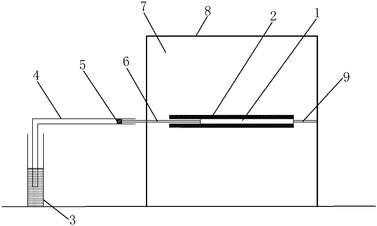
[0030] Such as figure 1 As shown, this embodiment takes the temperature measurement in the oven cavity as an example to describe the measuring device in the present invention. Specifically, the measuring device in this embodiment includes:

[0031] A temperature measuring element 1 with thermal expansion and contraction characteristics, at least the first end of the temperature measuring element is placed in the oven cavity in the temperature measuring state;

[0032] A measuring cylinder 3 with a scale is located outside the oven cavity 7, and the measuring cylinder is loaded with liquid; wherein, the liquid in this embodiment is water;

[0033] The conduit 4 is located outside the oven chamber 7, and the first end of the conduit 4 is inserted into the measuring cylinder 3 to below the liquid level of the liquid in the measuring cylinder; ...


PUM


Abstract

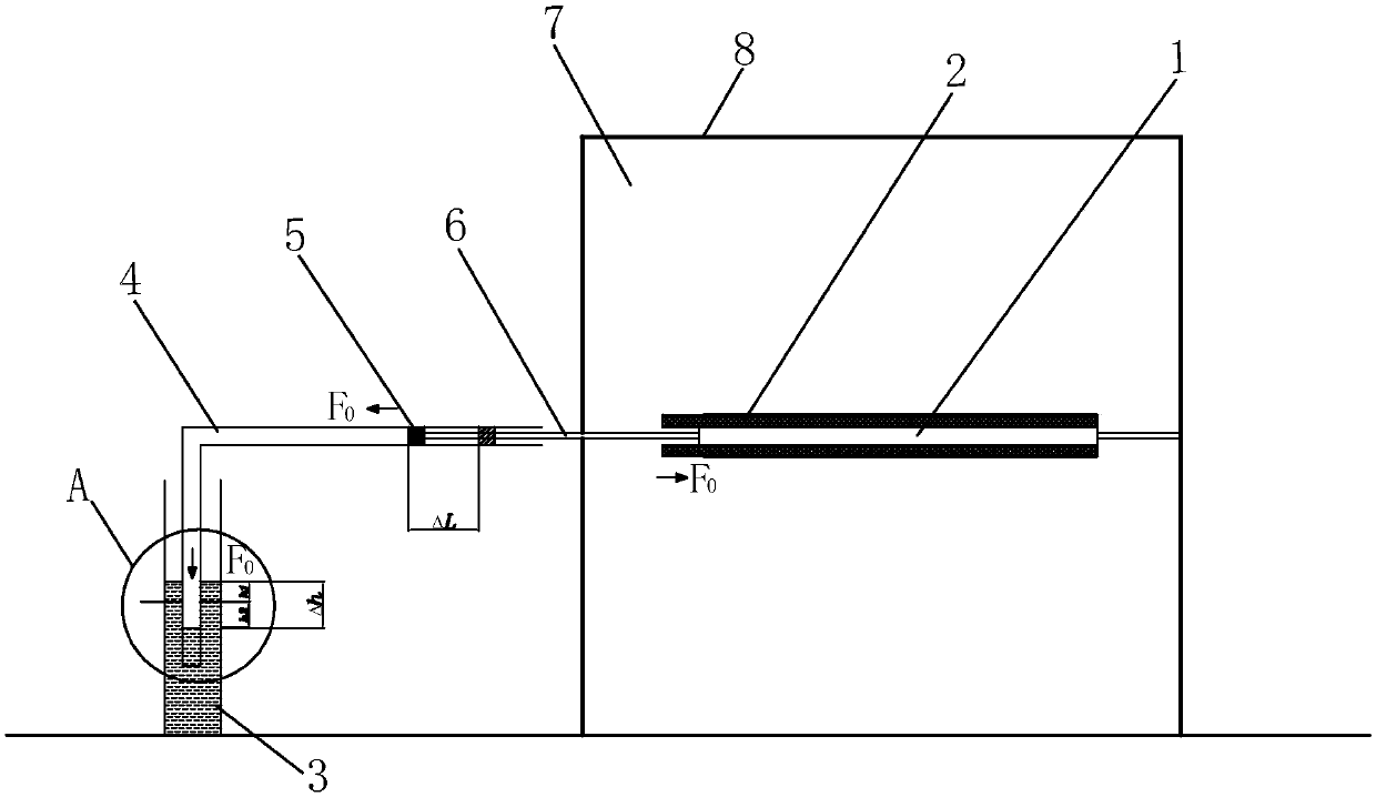
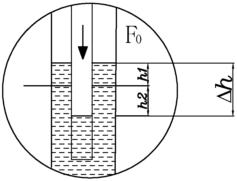
The invention relates to a device for measuring the temperature in an equipment cavity. The device comprises a temperature measuring element with thermal expansion and cold contraction characteristics, a measuring cylinder, a guide pipe, a piston and a first fixing rod, wherein the measuring cylinder and the guide pipe are located outside the equipment cavity, the piston can move in the guide pipe, a first end of the first fixing rod goes into a second end of the guide pipe and is connected to the piston, at least first end of the temperature measuring element is placed in the equipment cavity, the first end of the guide pipe is inserted into the liquid level in the measuring cylinder, and a second end of the first fixing rod is connected to a second end of the temperature measuring element. According to the device, the temperature measuring element deforms when heated and expanded in the equipment cavity, then the first fixing rod drives the piston to move in the guide pipe so that the pressure in the guide pipe is increased and the water level in the guide pipe is reduced, and then the temperature in the equipment cavity is accurately obtained according to the water level changesituation inside and outside the guide pipe and the function relation between the object deformation quantity and the temperature.

Description

technical field [0001] The invention relates to the field of temperature measurement, in particular to a device for measuring the temperature in an equipment chamber. Background technique [0002] At present, equipment that requires heating, such as ovens and steamers, has gradually become an important kitchen appliance in life, and people are more and more fond of using these equipment to make various delicacies. [0003] During the experimental testing of these devices, it is usually necessary to accurately measure the temperature in the chamber when the device is in operation, so as to verify various performance indicators of the device. At present, contact measurement methods and non-contact measurement methods are mainly used for temperature measurement in the cavity of equipment. Contact measurement methods mainly include electrical temperature measurement, photoelectric temperature measurement, thermochromic temperature measurement and other methods; non-contact temp...

Claims


Application Information

Patent Timeline
IPC IPC(8): G01K5/44G01K1/14
CPCG01K5/44G01K1/14
Inventor 陆枫
Owner NINGBO FOTILE KITCHEN WARE CO LTD
Learn More