
A continuous stamping method for sheet metal

A technology of stamping forming and sheet metal, applied in the field of stamping

Active Publication Date: 2021-04-23
TAICANG TAOXIN INFORMATION TECH CO LTD
View PDF10 Cites 0 Cited by
  • Summary
  • Abstract
  • Description
  • Claims
  • Application Information

AI Technical Summary

Problems solved by technology

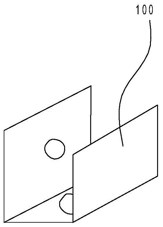
[0005] There is an existing U-shaped connector with a U-shaped cross-section, and through holes are respectively provided on the side wall and bottom of the U-shaped connector. At present, there is no special mold and stamping method for this connector. Continuous bending and punching operations

Method used


Image

  • A continuous stamping method for sheet metal
  • A continuous stamping method for sheet metal
  • A continuous stamping method for sheet metal

Examples


Embodiment Construction

[0027] The present invention will be further described in detail below in conjunction with the accompanying drawings and embodiments.

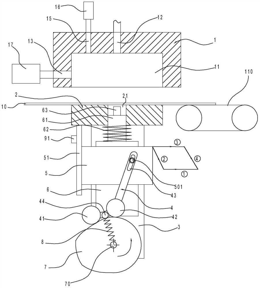
[0028] Firstly, a brief description will be given of the sheet material continuous stamping and forming device involved in the present invention. Such as Figures 1 to 11 As shown, the plate continuous stamping and forming device in this implementation includes an upper mold 1, a lower mold 2, a driving cam 7, a fixed plate 3, a horizontal slide 5, a vertical slide 6, a bending rod 4, a first roller 41, a second roller Post 42, compression spring 8, support rod 51, left punch 91, stamping spring 62, upper punch 63, suction pump 17 and blowing pump 16.

[0029] Among them, please combine figure 1 , 6 And 7, the upper die 1 of the present invention is fixedly arranged, and the lower die 2 is movable, and the upper die 1 is formed with a cavity 11 with a downward opening for U-shaped bending of the plate 10. In the cavity The bottom of 11 is ...


PUM


Abstract

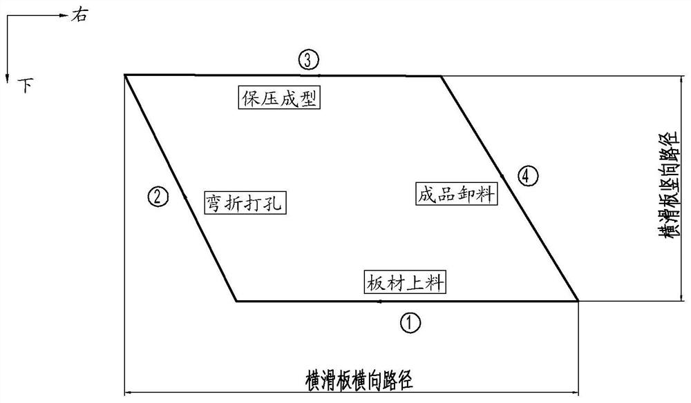
The invention discloses a method for continuous punching and forming of plates, which is characterized in that it comprises the following steps: Step S1, the conveying platform loads the plates piece by piece; Step S2, the near arc section on the driving cam contacts with two rollers , the plate is loaded to the top of the lower die; step S3, the plate is bent and punched, the first transition section on the driving cam gradually contacts with the two rollers, the vertical slide gradually moves upwards, and the plate is bent, after that, As the vertical slide continues to move upward, the upper punch punches the bottom of the U-shaped connector, and at the same time, the horizontal slide moves to the left, and the left punch punches the side wall of the U-shaped connector; step S4, pressure-holding forming ; Step S5, unloading the U-shaped connector; Step S6, repeating steps S2 to S5, realizing automatic continuous punching of the plate. The invention provides a continuous stamping and forming method for plates, which realizes one-time bending and punching operations on U-shaped connectors.

Description

technical field [0001] The invention relates to the stamping field, in particular to a continuous stamping forming method for plates. Background technique [0002] For most conventional sheet metal parts, due to the multiple processing procedures involved, it is generally impossible to use a pair of molds for one-time stamping and forming. The usual method is to use composite molds for continuous stamping and forming. There are three main types of conventional composite molds: (1) punching composite molds such as blanking and punching composite molds; cutting and punching composite molds, etc.; (2) forming composite molds such as bending composite molds and composite extrusion molds; (3) Blanking and forming composite molds such as blanking, deep drawing composite molds; punching, flanging composite molds; deep drawing, trimming composite molds; blanking, deep drawing, punching, flanging composite molds, etc. [0003] As for the continuous stamping method of sheet metal, th...

Claims


Application Information

Patent Timeline
Patent Type & Authority Patents(China)
IPC IPC(8): B21D35/00B23P23/04
CPCB21D35/001B21D35/002B23P23/04
Inventor 郑六军
Owner TAICANG TAOXIN INFORMATION TECH CO LTD
Learn More